WOODWORKING · DIY · A HANDMADE HOME @grainbyjoy
GRAIN by JoyWOODWORKING PLANS · WORKSHOP STORIES · HOME
FIND YOUR NEXT GOOD THING
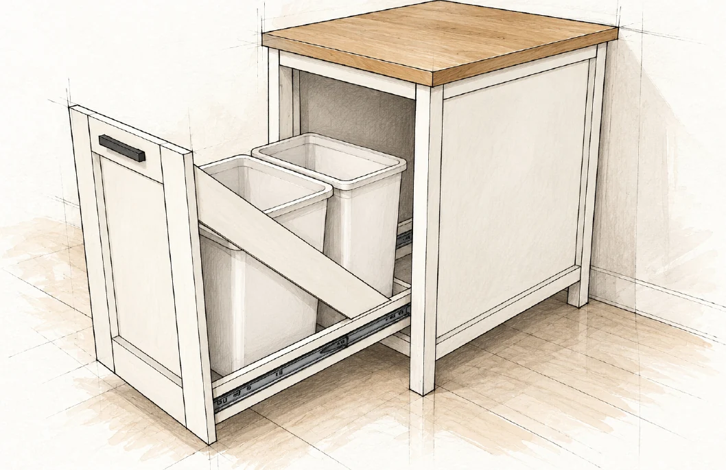
WOODWORKING PLANPullout Bin Kitchen Island
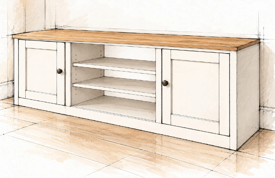
WOODWORKING PLANFarmhouse Media Console
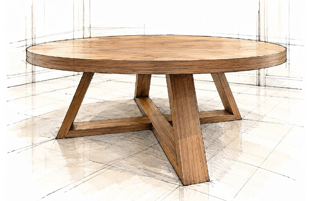
WOODWORKING PLANRound Coffee Table
WOODWORKING PLANGeometric Hairpin Coffee Table
WOODWORKING PLANHollow Panel Waterfall Console
WOODWORKING PLANFarmhouse Console Table
WOODWORKING PLANBarn Door Console
WOODWORKING PLANBeginner Farm Table
WOODWORKING PLANFarmhouse Coffee Table
FREE WOODWORKING PLAN
Benches / INTERMEDIATE

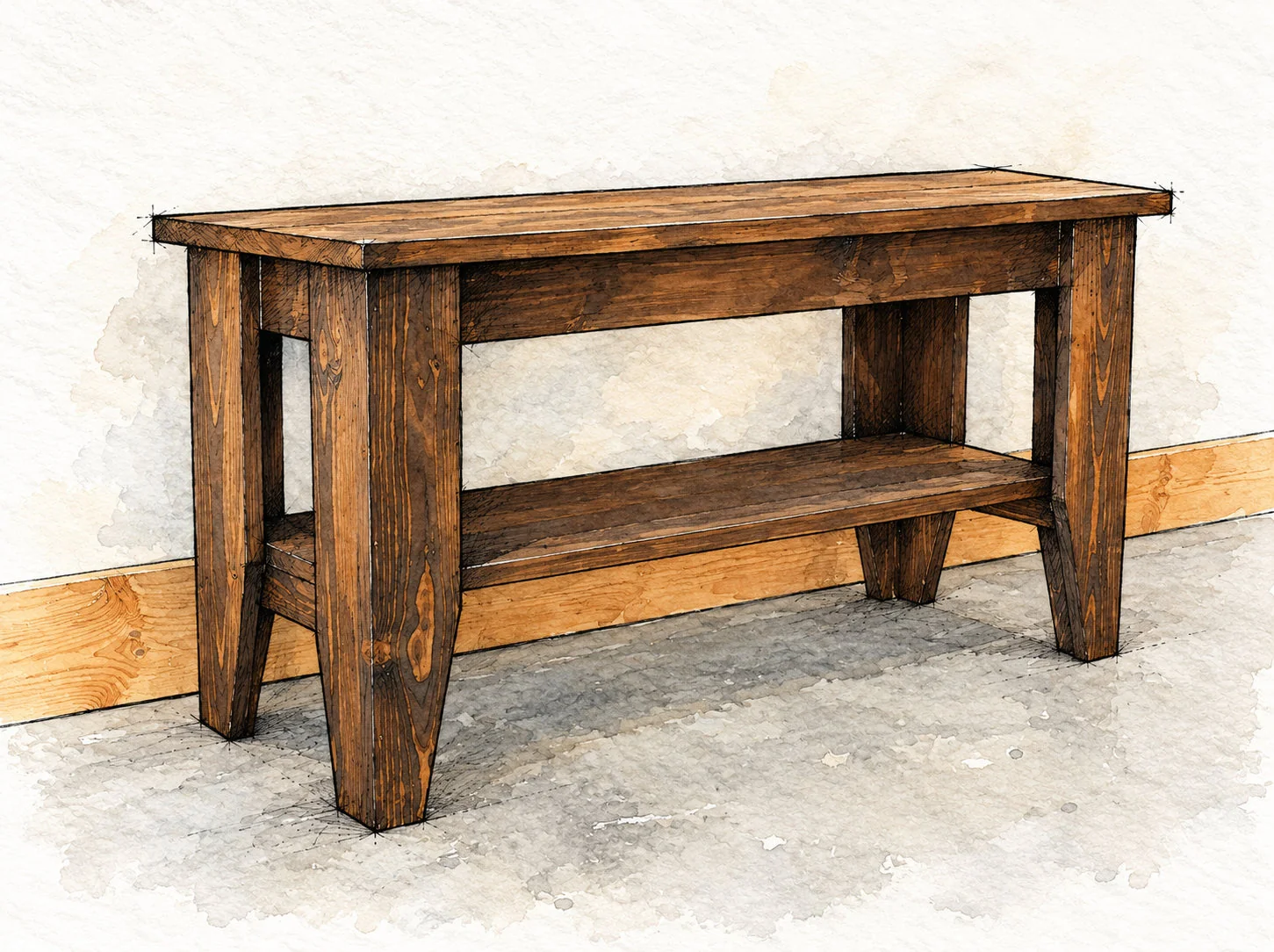
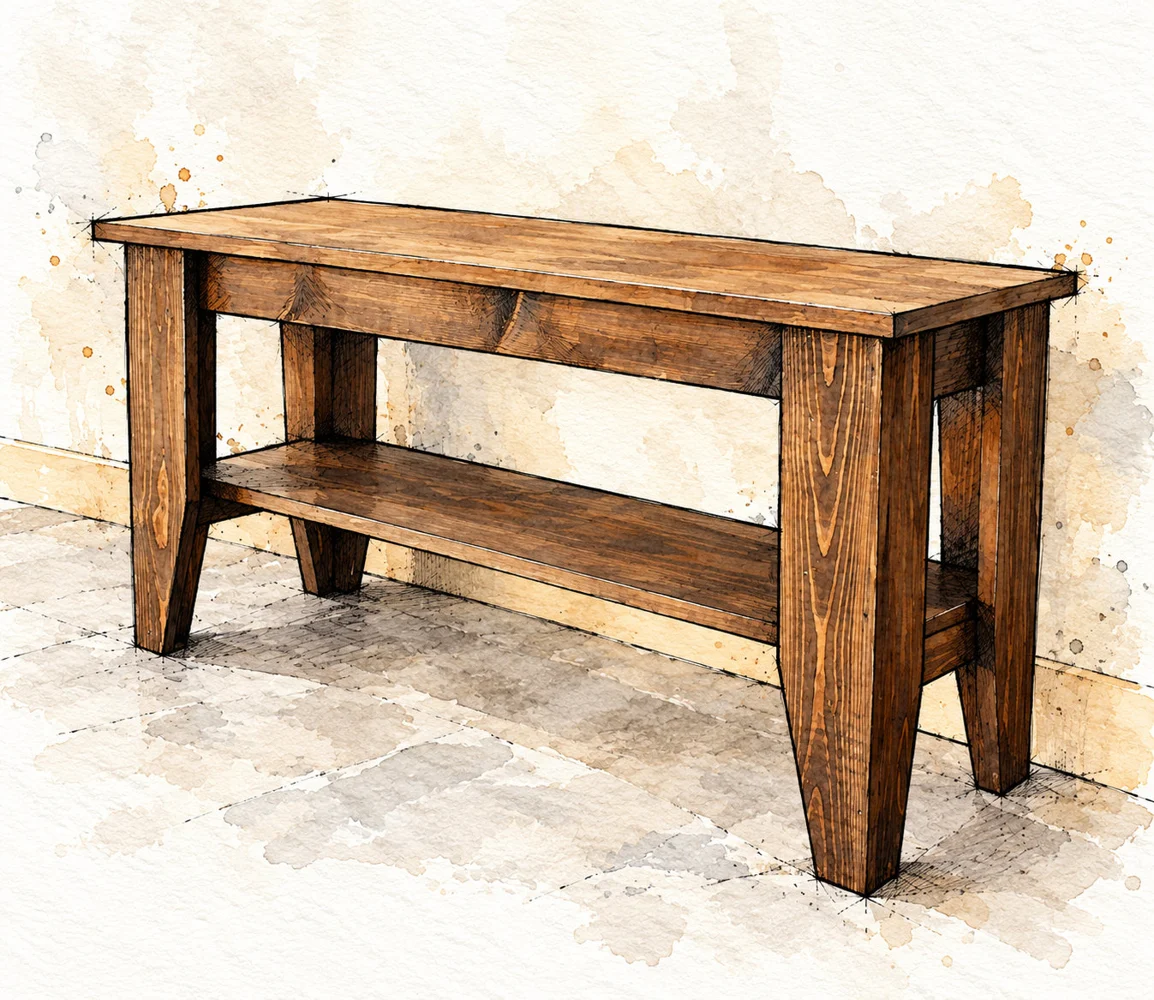
Simple Bench with Shelf

A compact indoor bench with tapered legs and useful storage underneath.

FINISHED DIMENSIONS35 × 15 × 18 3/4 in
SKILL LEVELIntermediate
WHAT IS INCLUDEDMaterials, cut list and illustrated steps
Read the free planMade this plan? Share your build
A GOOD BUILD STARTS WITH A CLEAR PLAN
  • Materials and tools
  • Cutting information and dimensions
  • Illustrated assembly steps
FROM THE FIRST CUT TO THE LAST DETAIL

Take it one step at a time

Everything you need to follow this build is written below. Read the materials, measurements and construction notes before your first cut.

Read the build steps

Yes. The complete plan is available to read on this page.
THE FREE BUILD GUIDE

Simple Bench with Shelf

A compact indoor bench with tapered legs and useful storage underneath.

PREPARE / SHOPPING LIST

Materials

Choose straight, dry boards and furniture-grade plywood. Inspect for splits, loose knots, bowing and twist before buying.

LUMBER AND PLYWOOD

• 1 × nominal 1×2, 8 ft long • 1 × nominal 1×3, 8 ft long • 2 × nominal 1×4, 8 ft long • 1 × 3/4 in (19.1 mm) plywood half-sheet, 48 × 48 in (1219.2 × 1219.2 mm), or suitable larger offcuts

FASTENERS AND CONSUMABLES

• 1 1/4 in (31.8 mm) wood screws for frame joints • 1 1/4 in (31.8 mm) finish nails for legs and shelf • Wood glue; optional iron-on veneer edge banding • Sandpaper, filler if needed, stain or paint, and a compatible interior clear finish

SEAT ATTACHMENT HARDWARE

Use four 90-degree L brackets and manufacturer-compatible wood screws for the actual seat and rail thickness. Bracket size, screw gauge, length and count depend on the chosen hardware. Buy these together; confirm the instructions before assembly.

DO NOT BUY AN EXACT 24 BY 48 IN PANEL

The nominal panel widths, 15 + 9 in, total 24 in (609.6 mm) before saw kerf. A 24 in-wide panel cannot yield both exact widths. The larger panel allows the stated cuts and trimming.

PREPARE / WORKSHOP SETUP

Tools and safe working

Read the complete guide and the instructions for each tool, fastener, adhesive and finish before starting.

TOOLS FOR THIS BUILD

Miter saw for square crosscuts; circular saw with a secure guide for plywood and tapers; drill/driver, suitable pilot and countersink bits; finish nailer compatible with the nails; tape measure, square, pencil, straightedge, clamps and a flat work surface.

SANDING AND EDGE BANDING

Use a sander or sanding block, dust extraction, and an iron plus trimming tools if adding iron-on banding. Follow the banding maker’s heat settings. Clamp the panel securely and keep fingers away from the hot soleplate and sharp trimming edge.

CUT AND FASTEN SAFELY

Wear eye and hearing protection and suitable dust protection. Support both the workpiece and offcut. Keep guards working, hands out of the cutting path and cords clear. Disconnect power before blade changes or adjustments. Never hold a small taper offcut by hand near the blade.

NAILER AND DRIVER CHECKS

Disconnect the nailer before clearing jams. Keep your free hand away from the nail path; nails can deflect through a board side. Clamp joints instead of using fingers as a backstop. Pre-drill screw joints to reduce splitting and test depths on scraps.

PREPARE / PARTS A TO F

Cut list

Inches are the primary dimensions. Panel sizes are approximate starting sizes; confirm the fitted size on your assembled frame.

PartQtyStockCut size and use
A81×418 457.2 Leg pieces
B21×311 279.4 Upper end braces
C21×211 279.4 Shelf supports
D21×330 762.0 Front and back rails
E13/4 in plywood31 1/2 × 9 800.1 × 228.6 Shelf panel
F13/4 in plywood35 × 15 889.0 × 381.0 Seat panel

CUT THE LEG PIECES SQUARE FIRST

Each corner leg uses two A pieces. Cut eight pieces to 18 in (457.2 mm), then mark the optional taper on each. Keep their full-width top ends square and their lengths equal.

ALLOW FOR THE SAW CUT

Do not lay cut marks end to end without allowing for blade kerf. Keep the saw on the waste side and trim one test part before repeating. Label parts lightly on a hidden face.

PREPARE / MEASUREMENT NOTES

Know your stock

Nominal sizes are shopping names, not measured dimensions. Check every piece before laying out joints.

Nominal Typical actual size in Typical actual size mm

1×2 3/4 × 1 1/2 19.1 × 38.1

1×3 3/4 × 2 1/2 19.1 × 63.5

1×4 3/4 × 3 1/2 19.1 × 88.9

PLYWOOD AND OVERALL SIZE

Nominal 3/4 in plywood may measure thinner than 3/4 in (19.1 mm). Use the measured thickness for pilot depths and bracket screws. The target finished height is 18 3/4 in (476.3 mm): an 18 in frame plus a nominal 3/4 in seat.

STOCK LENGTH CHECK

8 ft = 96 in (2438.4 mm). Cut four 18 in leg pieces from each 1×4. The 1×3 yields two 30 in rails and two 11 in braces, totaling 82 in (2082.8 mm) before kerf. The 1×2 yields two 11 in supports.

PANEL FIT AND OVERHANG

The seat target is 35 × 15 in (889.0 × 381.0 mm). Center it for 1 in (25.4 mm) end overhangs and about 1 1/4 in (31.8 mm) at front and back. Dry-fit the shelf and allow for edge-band thickness before final trimming.

METRIC CONVENTION

Convert at exactly 25.4 mm per inch, rounded half-up to 0.1 mm. Use either fractional inches or metric consistently within one assembly. Illustrations are not to scale.

STEP 01 / VIEW 1 OF 4

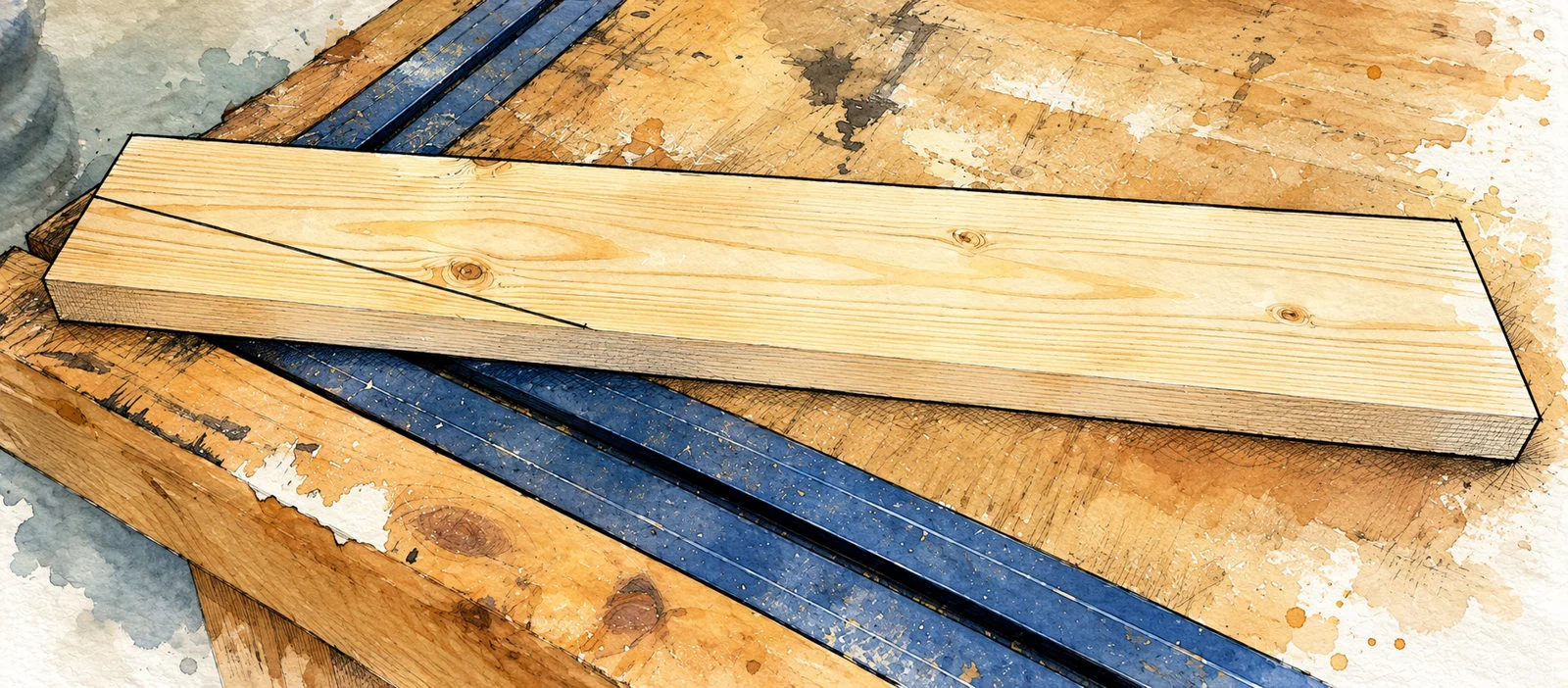
Mark the first corner leg

Mark the first corner leg · Simple Bench with Shelf

MEASURE FROM THE TOP

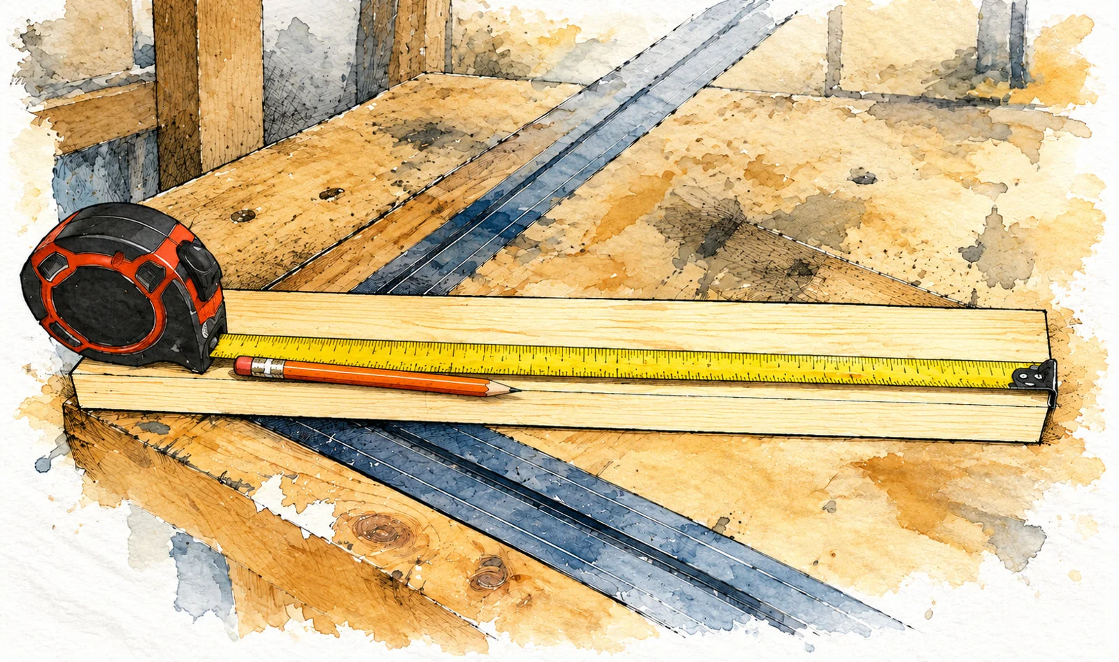
Choose two A pieces, each 18 in (457.2 mm) long. Mark the top ends so they remain easy to identify. Measure 11 in (279.4 mm) down from the top along the edge to be tapered, and make a clear pencil mark on each board.

WORK ON A FLAT SURFACE

The taper begins below this mark; the upper 11 in stays full width. Clamp or steady the board for marking, check the tape hook is seated against the top end, and verify the measurement before drawing the cut line.

CHECK BEFORE CONTINUING

Both pieces must be the same length. The taper is optional; square legs use the same assembly sequence.

STEP 01 / VIEW 2 OF 4

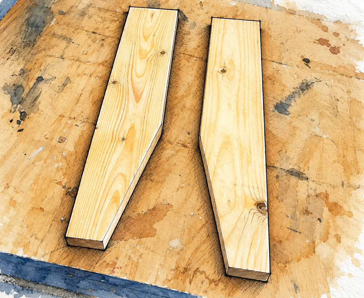
Draw the taper line

Draw the taper line · Simple Bench with Shelf

LOCATE THE BOTTOM CENTER

Measure the actual width at the bottom end of each board and mark its center. For a typical 3 1/2 in (88.9 mm) wide 1×4, the center is 1 3/4 in (44.5 mm) from either side. Use the actual center if your board differs.

JOIN THE TWO MARKS

With a straightedge, draw one line from the 11 in (279.4 mm) edge mark to the center of the bottom end. Mark the triangular waste clearly. Keep the straight outside edge intact so the finished leg has a consistent outer outline.

CHECK BEFORE CONTINUING

Do not estimate an angle from the picture. The two marked endpoints define the taper.

STEP 01 / VIEW 3 OF 4

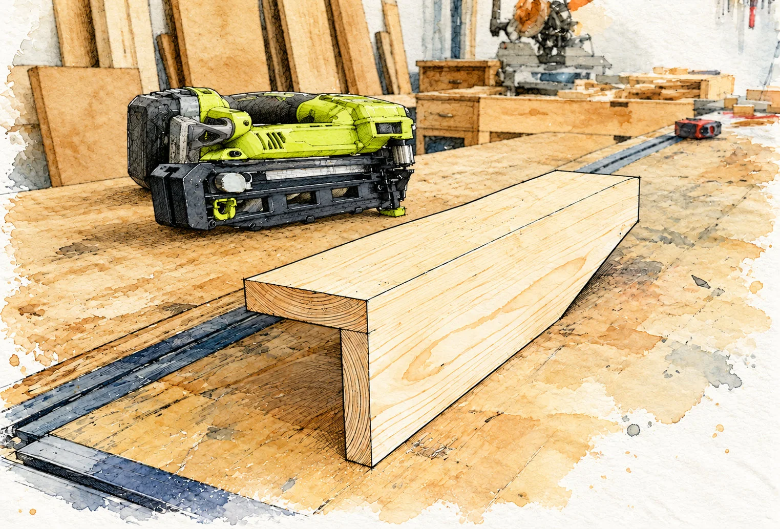
Cut and smooth the tapers

Cut and smooth the tapers · Simple Bench with Shelf

SECURE THE BOARD

Support and clamp one marked board with the cutting path clear of the work surface. Use a guided circular saw or another suitable saw with a secure, manufacturer-approved setup. Cut on the waste side of the line; let the blade stop before lifting or moving the work.

MAKE THE SECOND MATCHING PIECE

Repeat for the other board. Sand the sawn edges smooth and remove splinters, but do not round the long edge that forms the corner joint. Lay the two pieces together and compare the taper starts, bottom widths and overall lengths.

CHECK BEFORE CONTINUING

Keep both top ends square. A taper should change width, not shorten the leg.

STEP 01 / VIEW 4 OF 4

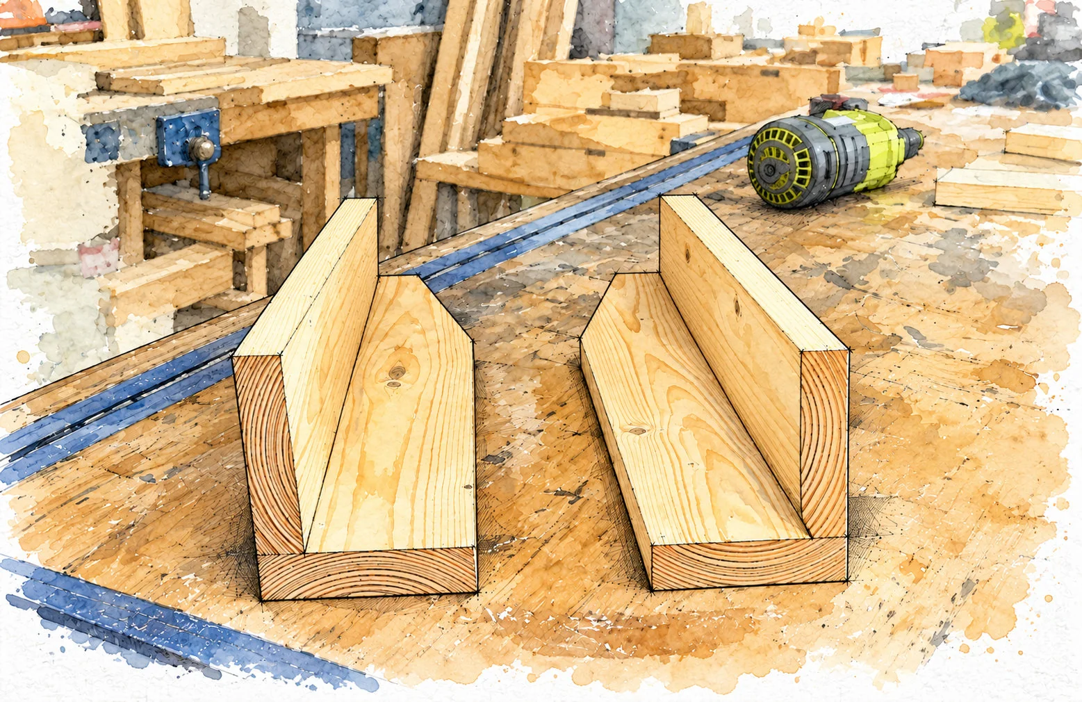
Glue the first corner leg

Glue the first corner leg · Simple Bench with Shelf

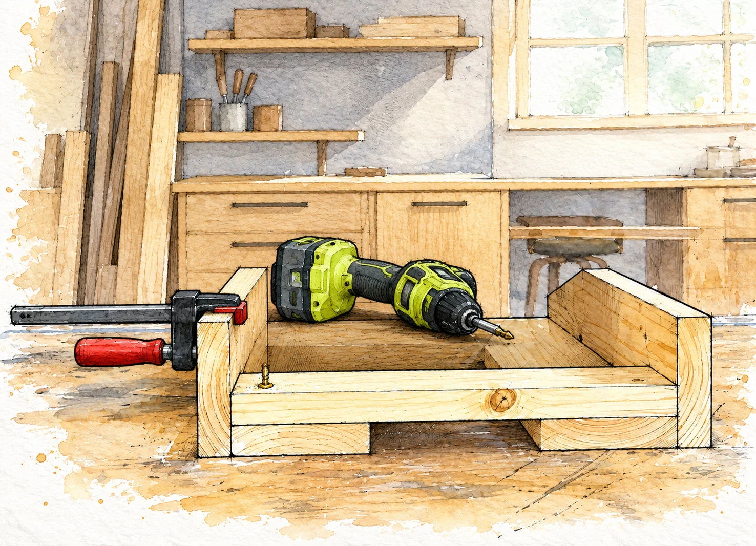
MAKE AN L SHAPED CORNER

Arrange the two tapered boards at a right angle. The long edge of one meets the broad inside face of the other; it is an overlapping corner joint, not a miter. Keep the top ends flush and orient the tapers toward the lower inside edges as shown.

CLAMP AND NAIL

Apply wood glue to the mating edge, bring the joint together and clamp it square. Drive 1 1/4 in (31.8 mm) finish nails through the overlapping face into the mating edge. Test depth on scraps and keep nails aligned away from board edges and your hand.

CHECK BEFORE CONTINUING

Wipe away squeeze-out and let the glue cure as directed. Each leg contains exactly two boards.

STEP 02 / VIEW 1 OF 1

Make the mirrored leg

Make the mirrored leg · Simple Bench with Shelf

REVERSE THE OVERLAP

Prepare two more A pieces using the same taper layout and cutting method. Dry-assemble them beside the first leg before applying glue. The new corner must mirror the first, with the full outer board faces on opposite sides.

CHOOSE THE VISIBLE FACES

On the completed bench, the uninterrupted 1×4 faces point toward the front and back; the visible overlap seams point toward the short ends. Glue, clamp square and nail the second leg in this reversed orientation. Keep the top ends and overall length aligned with the first leg.

CHECK BEFORE CONTINUING

Check the pair together before glue sets. Do not make two legs of the same handedness for one end.

STEP 03 / VIEW 1 OF 2

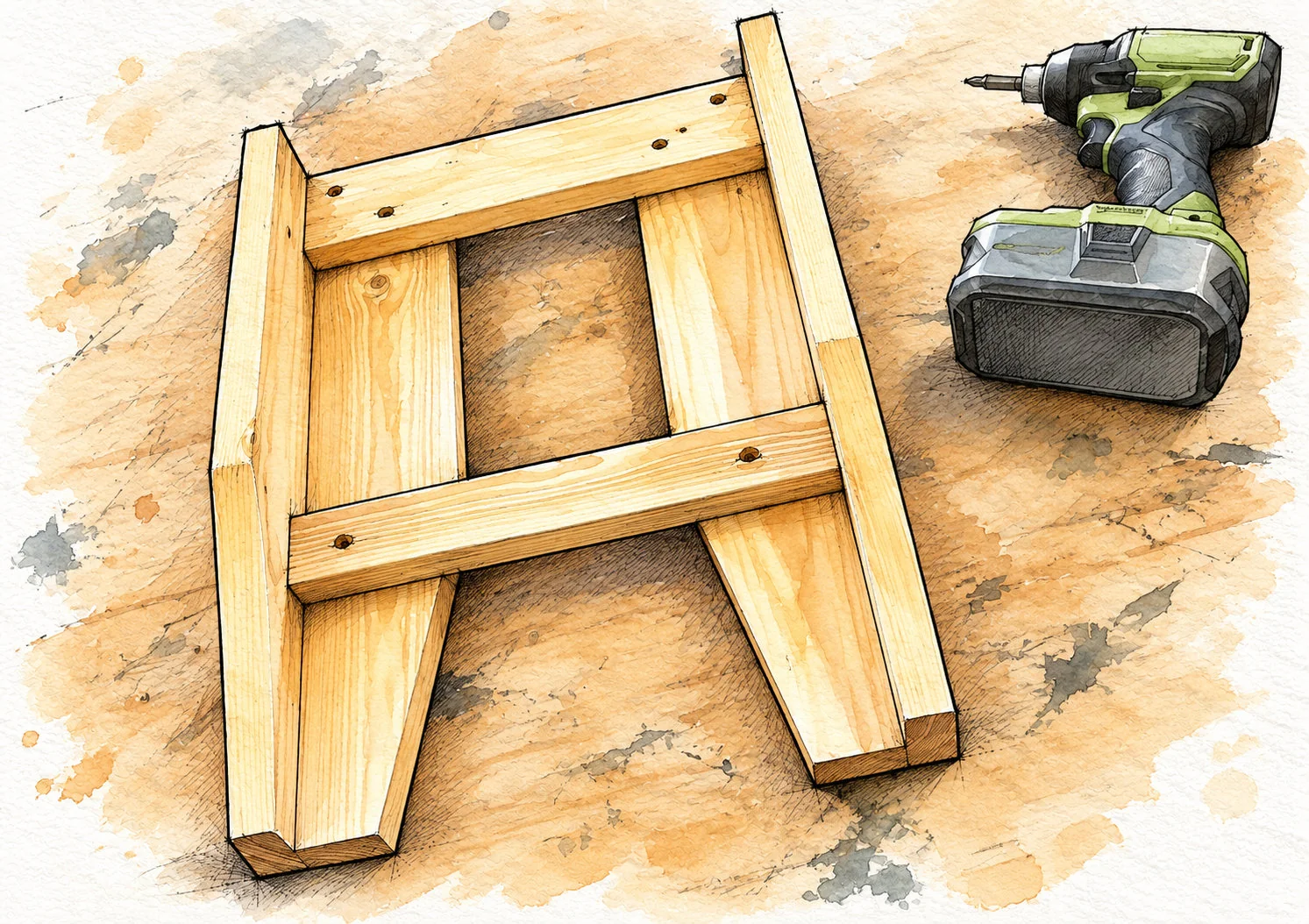
Attach the upper end brace

Attach the upper end brace · Simple Bench with Shelf

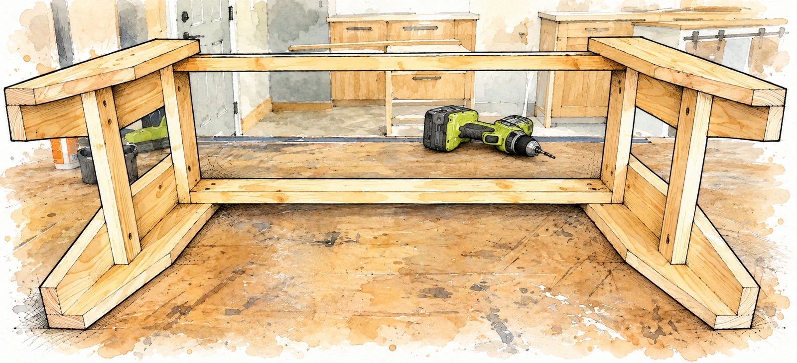
POSITION THE FIRST PAIR

Cut one B brace from nominal 1×3 to 11 in (279.4 mm). Lay the mirrored corner legs together to form one short-end frame. Place B against the inside faces of the legs with its ends overlapping them. Keep its upper edge flush with both leg tops.

GLUE AND SCREW THE OVERLAP

Clamp the assembly flat and square. Apply glue at each contact area, pre-drill and countersink as appropriate, then use 1 1/4 in (31.8 mm) wood screws through the brace face into the leg faces. Keep the screws within the overlapping wood, not the open corner.

CHECK BEFORE CONTINUING

The brace overlaps the legs. Do not shorten it to create a different end-to-end butt joint.

STEP 03 / VIEW 2 OF 2

Add the shelf support

Add the shelf support · Simple Bench with Shelf

SET THE LOWER BRACE HEIGHT

Cut one C support from nominal 1×2 to 11 in (279.4 mm). Measure about 11 in (279.4 mm) down from the top of each leg and mark the top edge position of C. This measurement is to the support’s top edge, not its center or bottom.

KEEP BOTH ENDS LEVEL

Place C against the inside faces of the legs with its ends overlapping them, parallel to the upper brace. Glue, clamp and secure with 1 1/4 in (31.8 mm) wood screws through its face into the legs. Check the frame with a square before tightening fully.

CHECK BEFORE CONTINUING

Both ends of the shelf support must be at the same height. The shelf will rest on its top edge.

STEP 04 / VIEW 1 OF 1

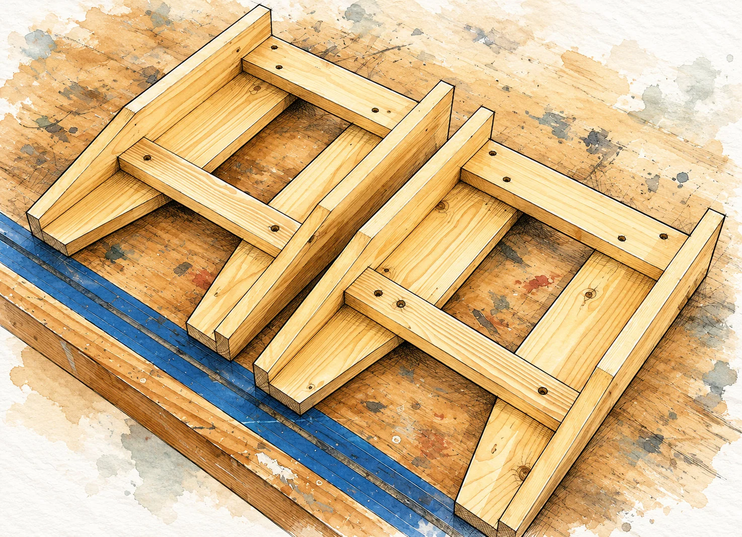
Build the second end frame

Build the second end frame · Simple Bench with Shelf

REPEAT THE MATCHED PARTS

Use the remaining four A pieces to make another mirrored pair of corner legs. Add the second 11 in (279.4 mm) B upper brace and the second 11 in C shelf support using the same overlap joints, glue and 1 1/4 in (31.8 mm) screws.

COMPARE THE FRAMES

Lay both finished end frames side by side on a flat work surface. Check that their leg tops, upper braces and shelf-support top edges align. Confirm that each frame is square and that the full board faces will face the front and back of the bench.

CHECK BEFORE CONTINUING

Correct any mismatch now. Unequal shelf-support heights would twist the shelf or leave one end unsupported.

STEP 05 / VIEW 1 OF 2

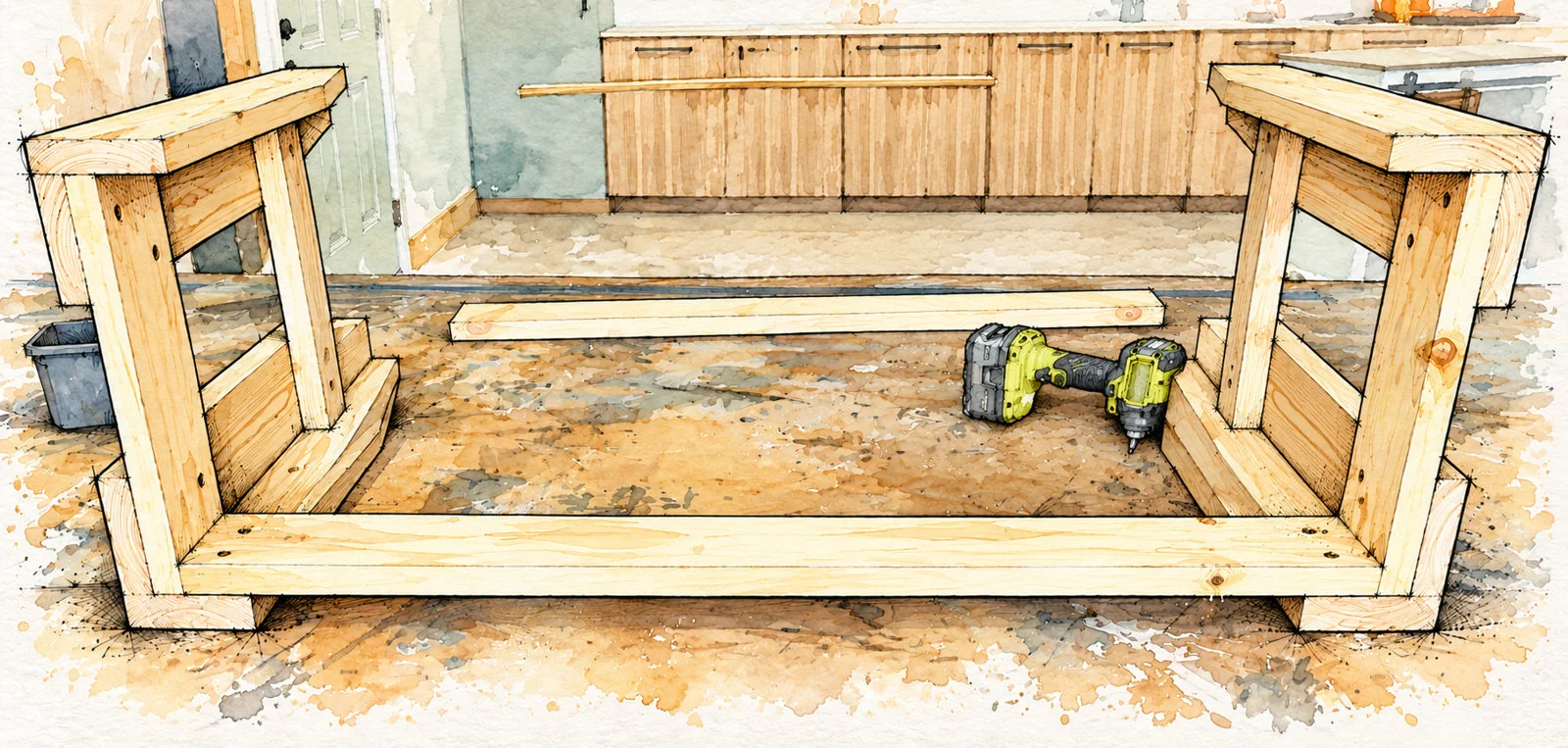
Join the end frames

Join the end frames · Simple Bench with Shelf

FIT THE FRONT SEAT RAIL

Cut two D rails from nominal 1×3 to 30 in (762.0 mm). Set the end frames on a stable surface and position the first rail against the inside faces of the front legs. Its ends overlap the leg faces, and its upper edge is flush with the leg tops.

CLAMP BEFORE DRIVING SCREWS

Hold the end frames parallel, apply glue at the contact areas and clamp the rail in place. Pre-drill and drive 1 1/4 in (31.8 mm) wood screws through the rail face into the legs. Keep screw paths clear of the existing end-brace screws.

CHECK BEFORE CONTINUING

The upper rail belongs inside the legs. Keep the outside leg faces and the leg-corner seams unchanged.

STEP 05 / VIEW 2 OF 2

Add the back seat rail

Add the back seat rail · Simple Bench with Shelf

COMPLETE THE UPPER FRAME

Attach the second 30 in (762.0 mm) D rail to the inside faces of the back legs. Use the same flush top alignment and overlapping joints, wood glue and 1 1/4 in (31.8 mm) screws. Support the frame while turning it; do not let a partly assembled joint carry its weight.

SQUARE THE WHOLE BASE

Before the glue sets, compare diagonals across the upper frame and adjust until they match. Check that the end frames remain parallel and all four feet contact a flat surface. Tighten screws snugly without crushing the wood or stripping the holes.

CHECK BEFORE CONTINUING

The top remains open at this stage. There are two long upper rails and no long lower rails.

STEP 06 / VIEW 1 OF 2

Dry fit the shelf

Dry fit the shelf · Simple Bench with Shelf

CUT THE PLYWOOD PANEL

Cut E from 3/4 in (19.1 mm nominal) plywood to about 31 1/2 × 9 in (800.1 × 228.6 mm). Support the sheet and guide the saw for square, clean cuts. Start slightly generous if the assembled opening differs, then trim carefully to fit.

SET IT ON THE SUPPORTS

Place the panel across the two C supports without glue or nails. It should sit flat at both ends and fit between the legs without forcing them apart. Mark the exposed edges and check the fit with the intended edge banding allowance. Remove the shelf after the test.

CHECK BEFORE CONTINUING

Do not attach the shelf yet. Finishing the frame and panels separately is easier.

STEP 06 / VIEW 2 OF 2

Cover the shelf edges

Cover the shelf edges · Simple Bench with Shelf

OPTIONAL EDGE BANDING

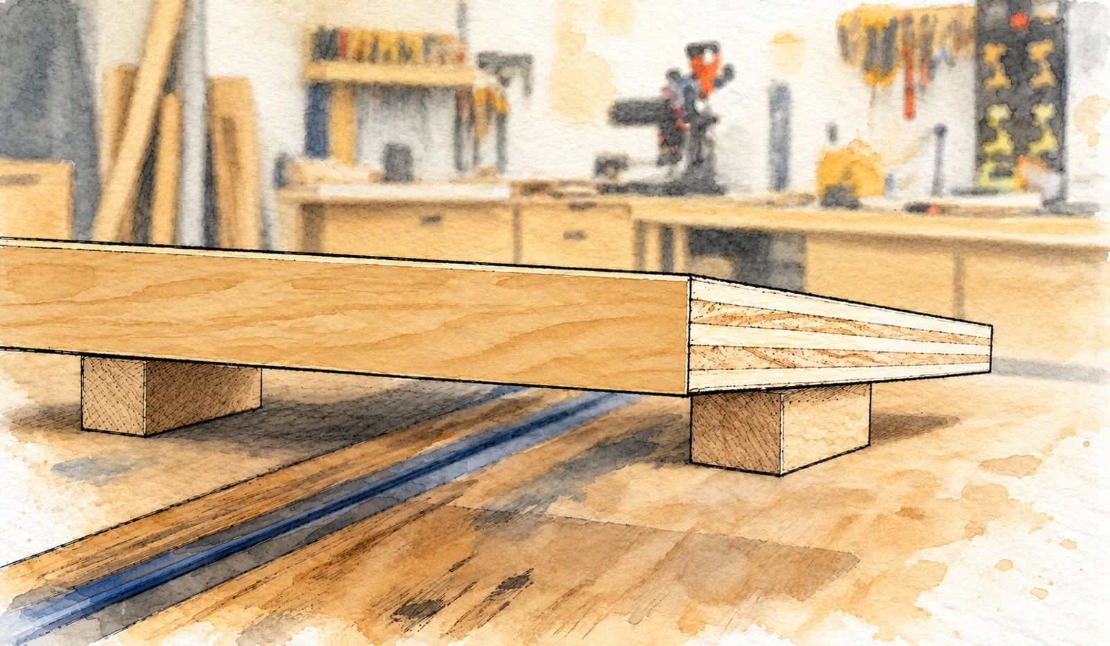
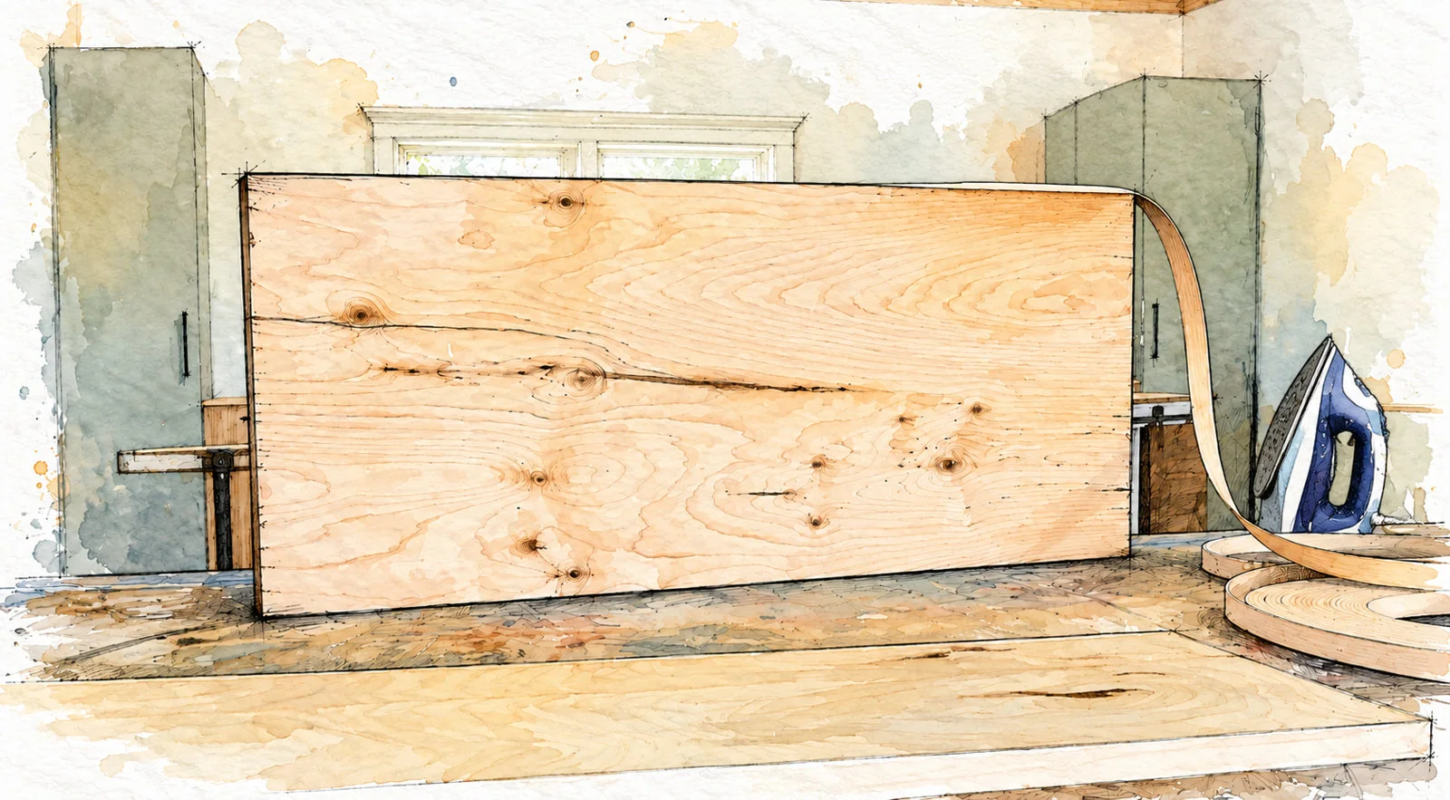
Iron-on veneer banding hides the visible plywood layers. The illustration contrasts a banded section with an exposed layered section. Smooth the plywood edge, clear away dust and cut the banding with trimming allowance at both ends.

APPLY AND TRIM CAREFULLY

Use the banding manufacturer’s iron setting and application method. Press the veneer firmly while the adhesive sets, let it cool, then trim the overhang flush without cutting into the plywood face. Lightly sand the edge. Dry-fit E again because banding adds a little width.

CHECK BEFORE CONTINUING

Leave the shelf loose. If you skip banding, sand and finish the exposed plywood edges instead.

STEP 07 / VIEW 1 OF 1

Prepare the seat panel

Prepare the seat panel · Simple Bench with Shelf

CUT AND FIT THE SEAT

Cut F from 3/4 in (19.1 mm nominal) plywood to about 35 × 15 in (889.0 × 381.0 mm). Test it on the upper frame. Center it for 1 in (25.4 mm) overhang at the two short ends and about 1 1/4 in (31.8 mm) at the front and back.

FINISH THE EDGES

Apply optional edge banding using the same method as for the shelf. Trim and lightly sand the banding flush. Smooth both faces, soften sharp corners slightly and label the underside where it will be hidden. Keep the seat separate until the frame is finished.

CHECK BEFORE CONTINUING

Use plywood for this guide. Do not substitute a solid-wood panel without redesigning its movement allowance.

STEP 08 / VIEW 1 OF 2

Finish the separate pieces

Finish the separate pieces · Simple Bench with Shelf

PREPARE THE SURFACES

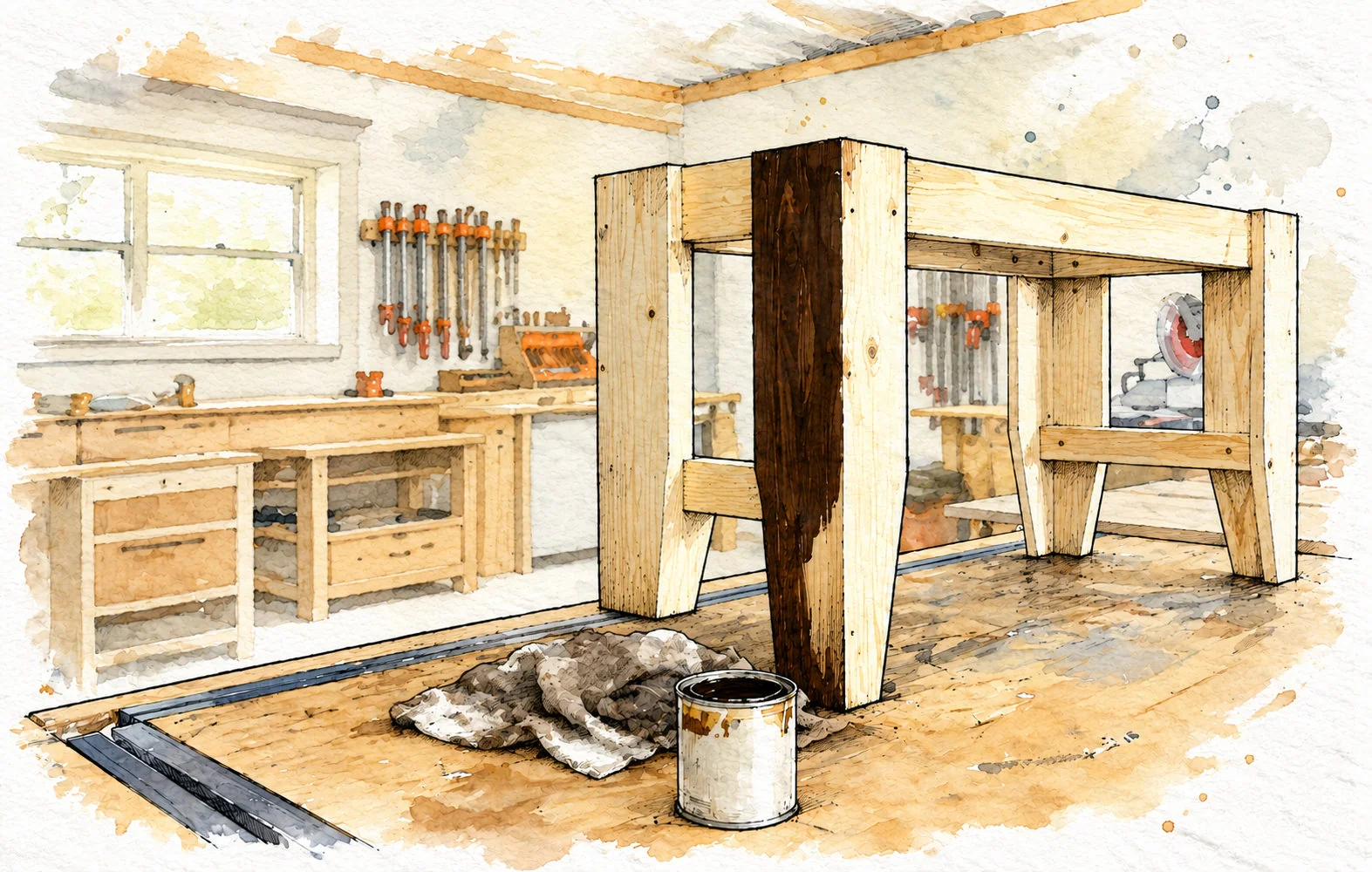
Sand the frame, shelf and seat smooth, remove dust and test your finish on matching scrap. Keep the shelf-support contact areas and matching underside patches bare if using wood glue there; glue will not form its intended bond over a finished surface.

APPLY COLOR SAFELY

Stain or paint the separate pieces. Follow product directions for ventilation, protection and drying. Avoid puddles inside corner legs. Keep finishes away from sparks and flame. Handle and dispose of oil-stained rags exactly as the label directs; never pile them up.

CHECK BEFORE CONTINUING

Let the finish dry as directed before handling or attaching the shelf. Reserve compatible clear finish for final protection.

STEP 08 / VIEW 2 OF 2

Secure the lower shelf

Secure the lower shelf · Simple Bench with Shelf

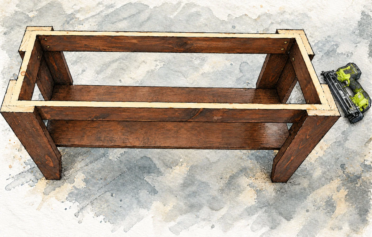
GLUE THE SUPPORT CONTACTS

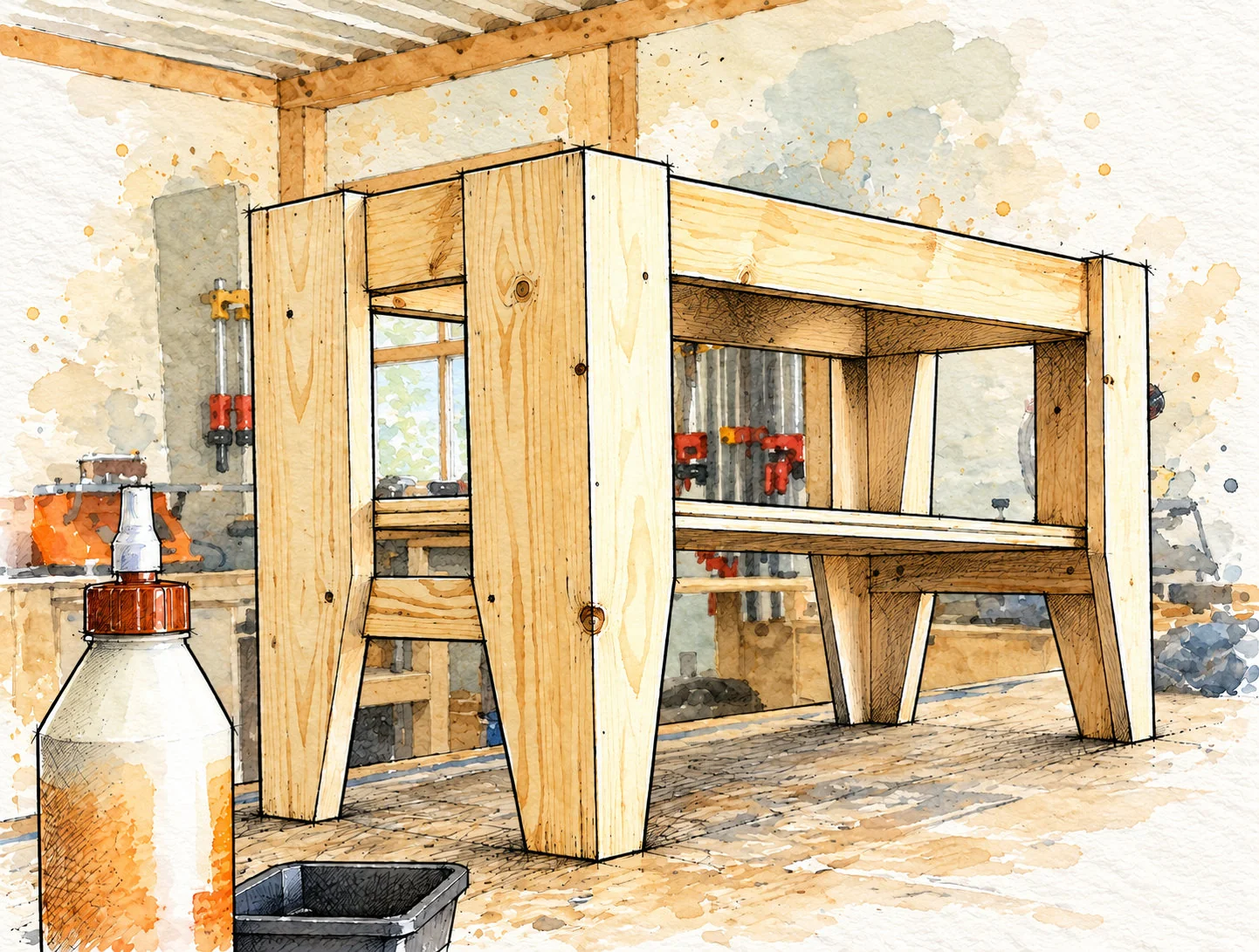
With the frame upright and stable, confirm E still fits. Apply wood glue along the bare upper edges of the two C shelf supports, then seat the shelf on them. Check that it lies flat and that its ends are properly supported.

NAIL INTO THE SUPPORTS

Drive 1 1/4 in (31.8 mm) finish nails down through the plywood into the supports. Locate the support below each nail before firing. Keep the nailer perpendicular to the joint and your hands out of the possible exit path. Use a scrap test to set nail depth without damaging the veneer.

CHECK BEFORE CONTINUING

Do not nail into an unsupported area of the shelf. Wipe away squeeze-out and allow the glue to cure.

STEP 09 / VIEW 1 OF 3

Attach the seat with brackets

Attach the seat with brackets · Simple Bench with Shelf

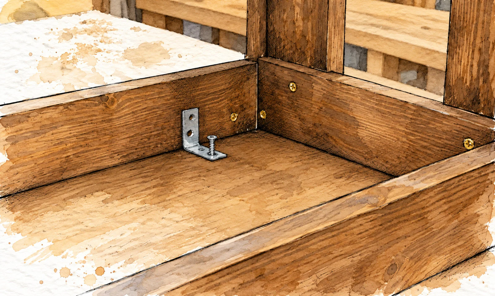
CENTER THE UPSIDE DOWN BASE

Protect the finished face and lay F upside down on a clean workbench. With help, turn the base upside down onto it. Center the base, recheck all overhangs and clamp gently. Position four 90-degree L brackets between the seat underside and the inside faces of the upper rails.

CHOOSE SCREWS BY THE HARDWARE

Use bracket-manufacturer-compatible screws and pilot depths for the measured plywood and rail thickness. Account for bracket thickness and keep every tip short of the opposite wood face. Do not use the general 1 1/4 in (31.8 mm) frame screws upward into the nominal 3/4 in seat.

CHECK BEFORE CONTINUING

Test the chosen screw and pilot depth on matching scraps. Do not guess from the illustrated screw size.

STEP 09 / VIEW 2 OF 3

Check all four seat brackets

Check all four seat brackets · Simple Bench with Shelf

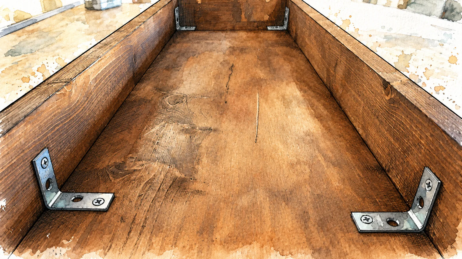
FASTEN BOTH WINGS

Use all four brackets, with each bracket’s horizontal wing against the seat underside and its vertical wing against a rail. Mark and drill pilot holes with a depth stop. Install the specified screws in the required bracket holes, following the hardware maker’s instructions.

INSPECT BEFORE TURNING UPRIGHT

Confirm each bracket lies flat and does not pull the seat out of position. Tighten screws snugly, not hard enough to strip the plywood or bend the brackets. Check from both sides that no screw tip or pilot hole has broken through the seat or the outer rail face.

CHECK BEFORE CONTINUING

The illustration shows the arrangement, not a hardware specification. Stop and correct any loose bracket, stripped hole or exposed tip.

STEP 09 / VIEW 3 OF 3

Finish and inspect the bench

Finish and inspect the bench · Simple Bench with Shelf

APPLY THE PROTECTIVE FINISH

Turn the bench upright with help. Add a compatible clear finish as needed, following its directions for preparation, coat thickness, drying and full cure. Inspect the seat and shelf edges for rough spots, remove any sharp splinters and check every joint and attachment.

USE IT WITH CARE

Set the bench on a level floor. All four feet should rest firmly, the shelf should be supported at both ends and the frame should not rack. No tested load rating is provided. Use as an indoor seat, not a step or a platform; do not stand or jump on it.

CHECK BEFORE CONTINUING

Wait for the finish and glue to cure fully. Recheck joints periodically and stop using the bench if it loosens or rocks.

MAKE IT YOURS

Measure your own stock and dry-fit before fastening. If you make this project, I would love to see what you built.

Share your build