Yes. The complete plan is available to read on this page.
THE FREE BUILD GUIDE
Storage Unit with Beveled Edge
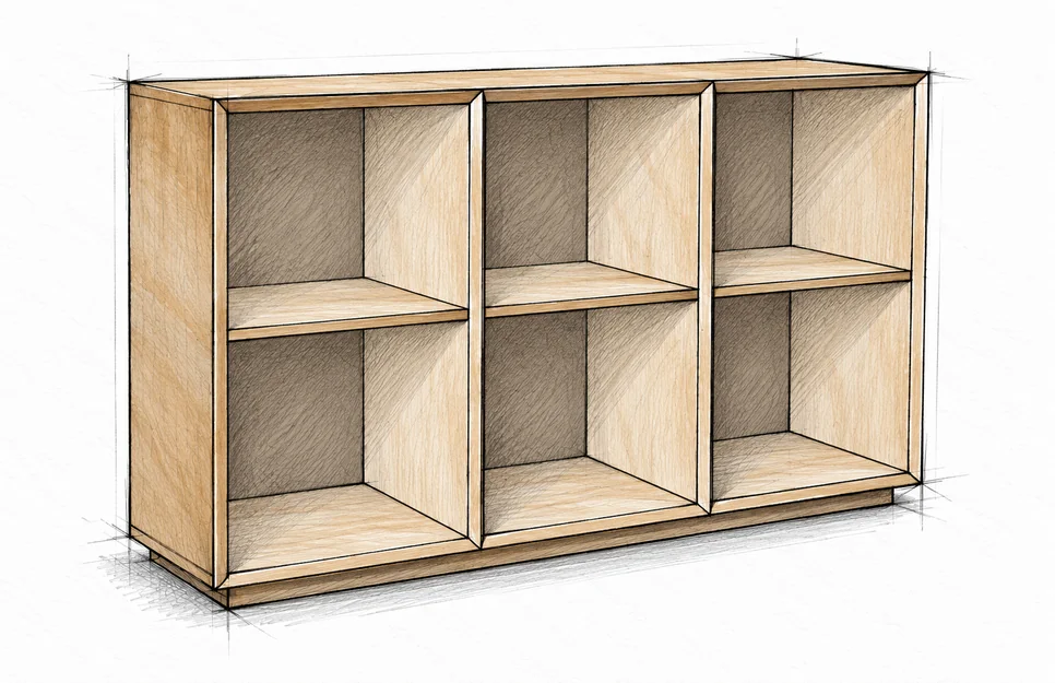
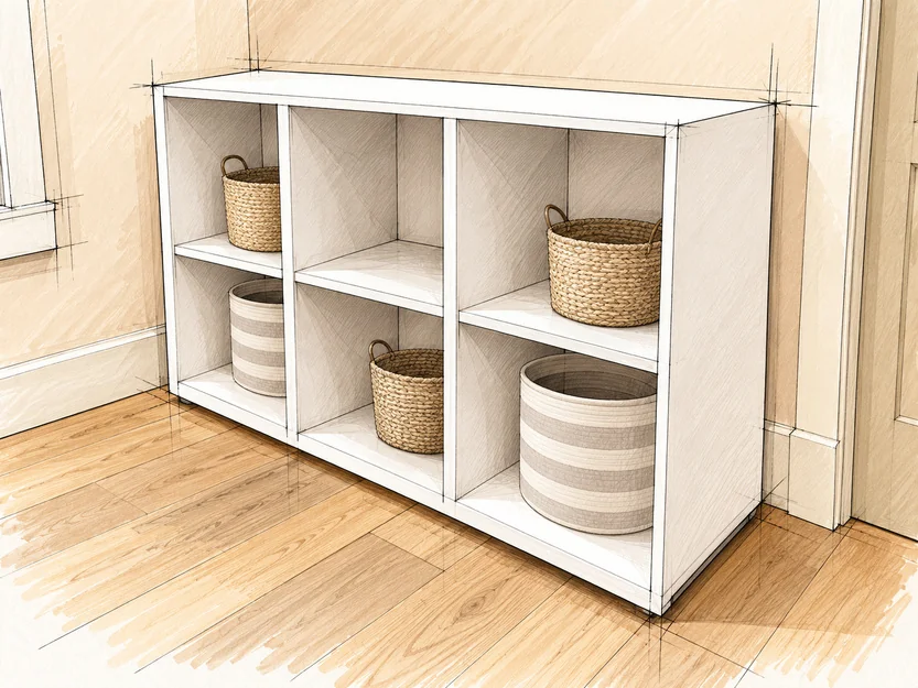
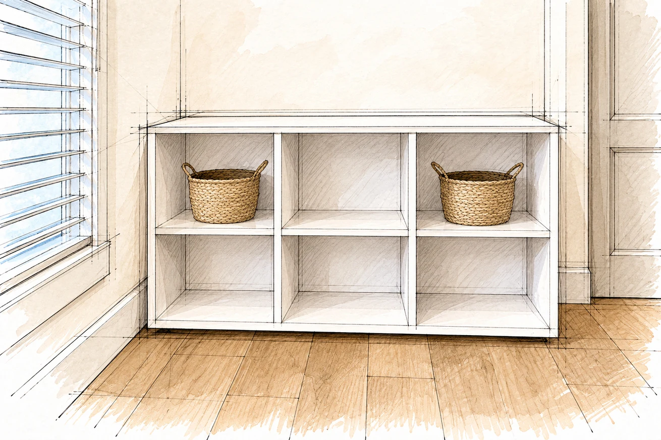
Six open cubbies, doubled dividers, beveled front edges, and a recessed base. The illustrated guide includes the trim and back-panel steps.
READ BEFORE CUTTING
Plan the build
What you will make
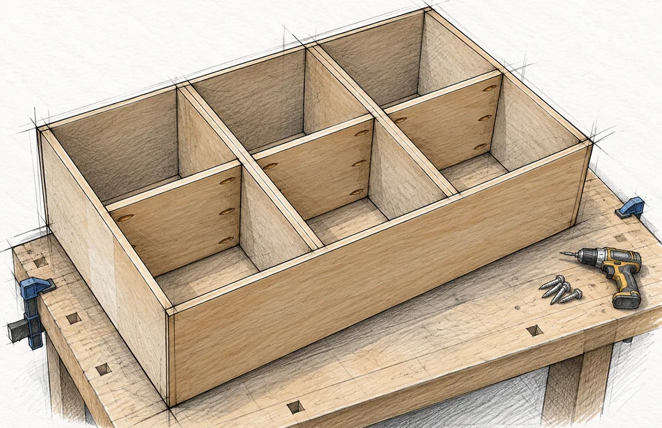
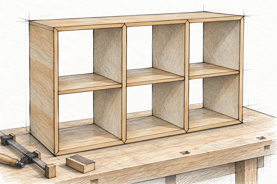
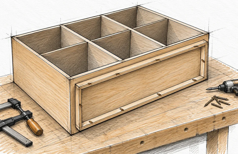
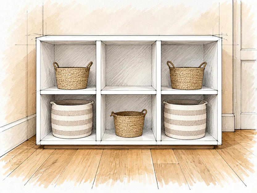
Three equal columns and two rows form six open cubbies. Each interior divider is made from two plywood panels laminated together. Three separate shelves divide the columns at midheight. A thin back squares the case; a recessed four-rail base raises it off the floor.
Choose the assembly sequence
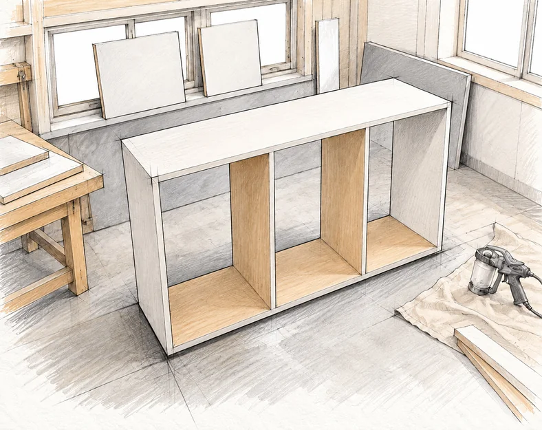
Follow the numbered assembly steps. The finishing views also show a prefinish option: paint the open case, loose shelves and back before final assembly. Keep glue surfaces bare. If using a colored finish, caulk compatible joints before the final topcoats.
Measure the stock you buy
Inches control the cuts. Millimetres are conversions rounded to 0.1 mm, not different tolerances. Board names are nominal; measure actual sizes. The design assumes ¾ in plywood. Dry-fit shelves to the actual bays before drilling. Choose optional baskets only after measuring the finished openings.
Plan for safe use
Obtain an anti-tip system and wall fixings suitable for the actual wall and structural furniture attachment points. Anchor the unit before loading it or allowing children access. It is storage furniture, not a seat, step or climbing structure. No load rating is specified.
STOCK FOR ONE PROJECT
Materials and fasteners
Choose flat, sound paint-grade plywood and straight, dry trim stock. Fastener and finish quantities depend on the chosen products and hole layout.
Quantity
Item
Size or specification
2 sheets
Carcass plywood
¾ in × 48 × 96 in 19.1 × 1219.2 × 2438.4 mm
1 panel
Shelf plywood
¾ in × 24 × 24 in 19.1 × 609.6 × 609.6 mm
1 sheet
Back plywood
¼ in × 48 × 96 in 6.4 × 1219.2 × 2438.4 mm
2 boards
Base stock
Nominal 1 × 2 × 8 ft Usually ¾ × 1½ in; 2438.4 mm
1 board
Beveled trim stock
Nominal 1 × 6 × 6 ft Usually ¾ × 5½ in; 1828.8 mm
As needed
Pocket screws
1¼ in / 31.8 mm; type compatible with the plywood and pocket-hole jig
As needed
Brad or pin nails
1¼ in / 31.8 mm. Trim: 18 ga brads or 23 ga pins. Back: 18 ga brads.
As needed
Wood glue and filler
Interior woodworking glue; paint-compatible filler for small surface defects
As needed
Caulk and finish
Paintable caulk, compatible primer and paint; follow product instructions
WORKSHOP SETUP
Tools and preparation
Tool
Purpose or requirement
Tape, pencil and square
Mark cuts and matching faces; check every panel for square.
Guided saw
Track saw, or circular saw with a suitable guide, to break down supported plywood sheets.
Table saw and safe ripping aids
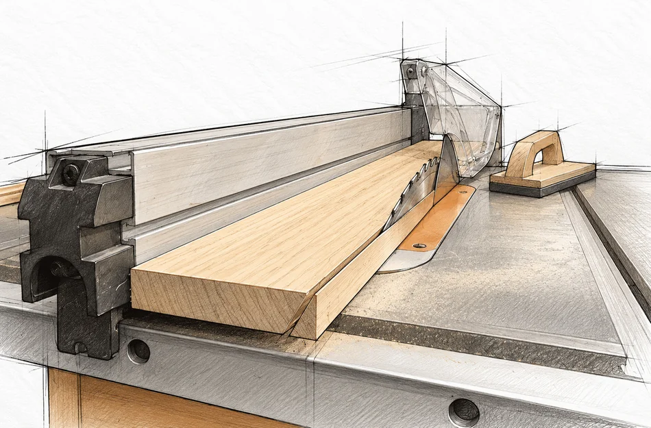
Make the 30° bevel strips using a suitable fence, push blocks and a safe narrow-rip setup.
Miter saw
Cut and fit the beveled trim miters. Support long strips and small offcuts safely.
Pocket-hole jig and drill
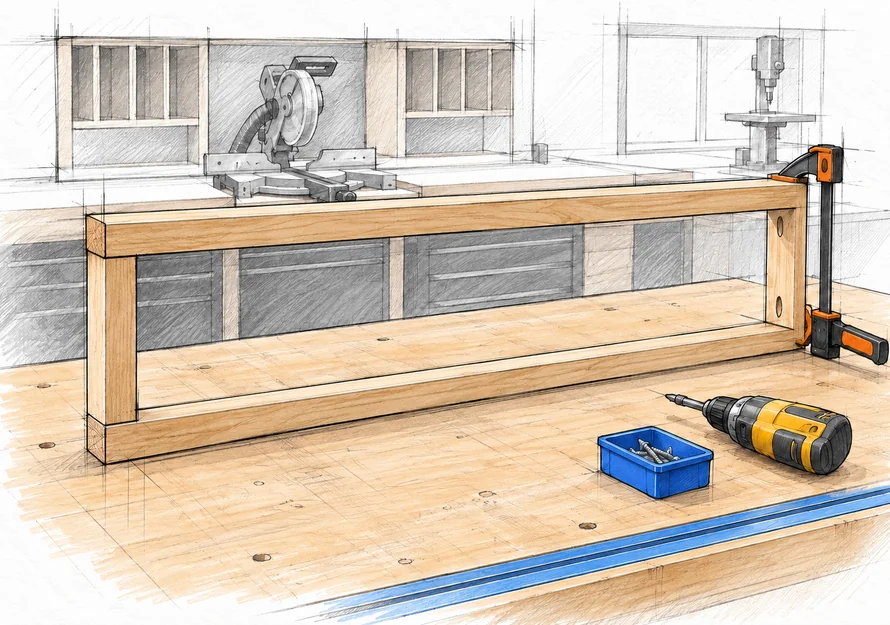
Set the jig and stop collar for actual stock thickness; drill and drive the pocket joints.
Brad nailer or pin nailer
Attach trim; use an 18 ga brad nailer for the thin back.
Clamps and straightedge
Hold joints flush and square; mark backing support lines.
Sanding and finishing tools
Sanding block or sander, dust extraction, putty knife, caulk gun and appropriate paint applicator.
WORKSHOP SETUP
Work safely
Protect yourself and support the work
Wear eye and hearing protection. Control dust with extraction and suitable respiratory protection. Fully support sheet goods and offcuts; clamp guides before cutting. Get help lifting and turning the case. Do not work under an unsupported assembly.
Make safe saw setups
Disconnect power before changing blades, bevel settings or fences. Use guards, a riving knife and push aids as required by the saw manufacturer. Never freehand a narrow bevel rip or reach across the blade. Stop if the last strip cannot be produced safely; obtain wider stock or qualified help.
Use fasteners carefully
Test pocket-hole settings in matching scrap. Clamp before driving screws and use a clutch setting that avoids stripping plywood. Keep hands clear of nail paths, including the far side where a nail could exit. Disconnect a nailer before adjusting or clearing it.
Prepare for finishing
Follow the filler, caulk, primer and paint labels for ventilation, protective equipment, drying and curing. Keep ignition sources away when required. The process illustrations show static tool setups, not safe hand positions for live operation.
CUT AND LABEL BEFORE ASSEMBLY
Cut list
Panel sizes are length × width; thickness is listed with the stock. Label each part after cutting. Six B panels make two outer sides and two doubled interior dividers.
Understand the six cubbies · Storage Unit with Beveled Edge
Read the structure
The top and bottom span the full width. Two side panels and two doubled dividers run between them. One shelf in each bay creates six openings. The back closes and braces the case.
Check the finished envelope
Allow for a nominal 60 × 18½ × 38 in unit (1524.0 × 469.9 × 965.2 mm). Actual back thickness and trim projection affect depth. Check baseboards, the wall anchoring position and access before building.
Lay out the plywood · Storage Unit with Beveled Edge
Mark every piece first
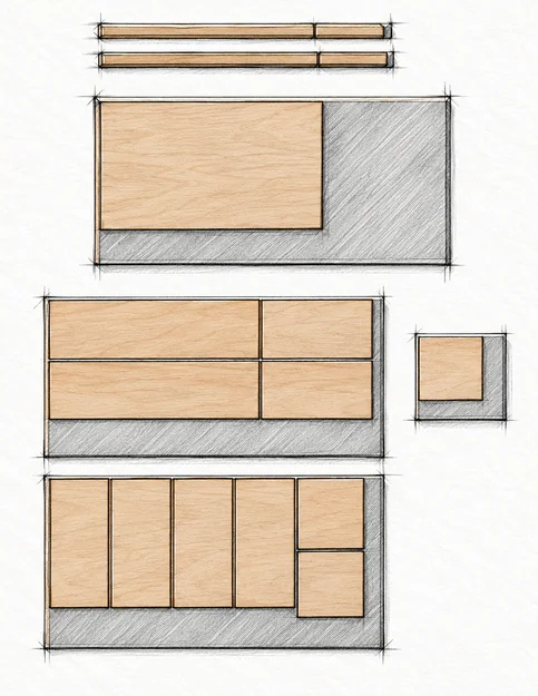
Use the cut list, not the sketch scale. On the first thick sheet, two 18 in strips each yield one 60 in A panel and one 35 in B panel. Leave room for blade kerfs and edge cleanup.
Use the remaining stock
The second thick sheet yields four B panels and two C shelves. Cut the third shelf from the 24 × 24 in panel. Cut the back from the thin sheet and the base rails from the two 1 × 2 boards.
Cut square panels · Storage Unit with Beveled Edge
Set the guide
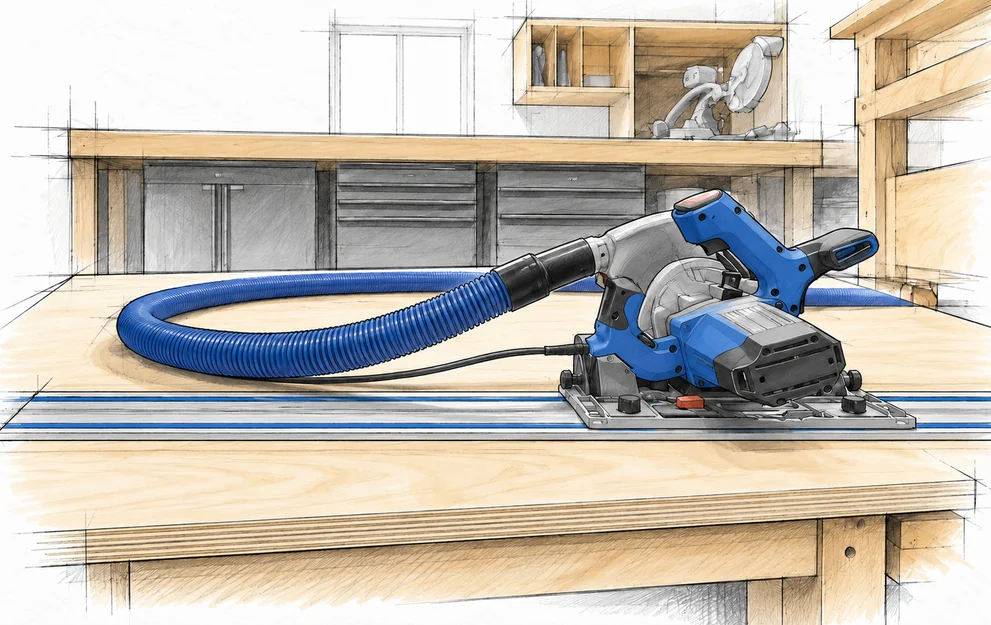
Mark the waste side, clamp the guide and check blade clearance below the sheet. Make a test cut in scrap. Support both sides of each cut so the sheet cannot sag or pinch the blade.
Match and label
Check diagonal measurements and square corners. Match the two A panels and all six B panels before assembly. Mark front edges and good faces; keep the three C shelves together.
Assemble the main case · Storage Unit with Beveled Edge
Locate the panels
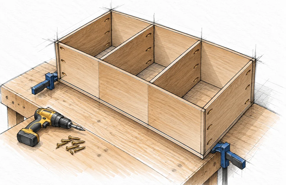
Fit two B sides between A top and bottom. Viewed from the front, set the right faces of the two initial B dividers at 20 and 40 in (508.0 and 1016.0 mm) from the left outside edge.
Drill and assemble
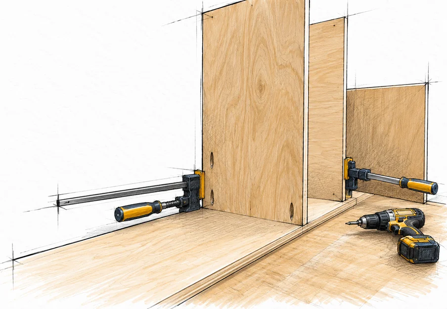
Point both interior divider pocket-hole faces to the right so the added layers will cover them. Glue, clamp square and drive 1¼ in (31.8 mm) pocket screws using the jig instructions.
Keep the case square · Storage Unit with Beveled Edge
Seat each joint
Keep panel ends tight against the top and bottom and the front edges flush. Clamp each joint before driving screws. Stop when seated; do not crush the plywood or strip the hole.
Check before proceeding
Compare case diagonals and correct any racking while the glue is workable. Keep the frame supported until the glue reaches its stated handling strength. Do not add the shelves yet.
Add the second layers · Storage Unit with Beveled Edge
Cover the pocket holes
Spread an even glue film on the mating face of each remaining B panel. Place one on the right face of each inner divider, covering the pocket holes. Align the top, bottom, front and rear edges.
Verify the bays
With true ¾ in plywood, both doubled dividers are 1½ in (38.1 mm) thick and all three clear bays are 18½ in (469.9 mm) wide. Check a shelf in every bay before the glue sets.
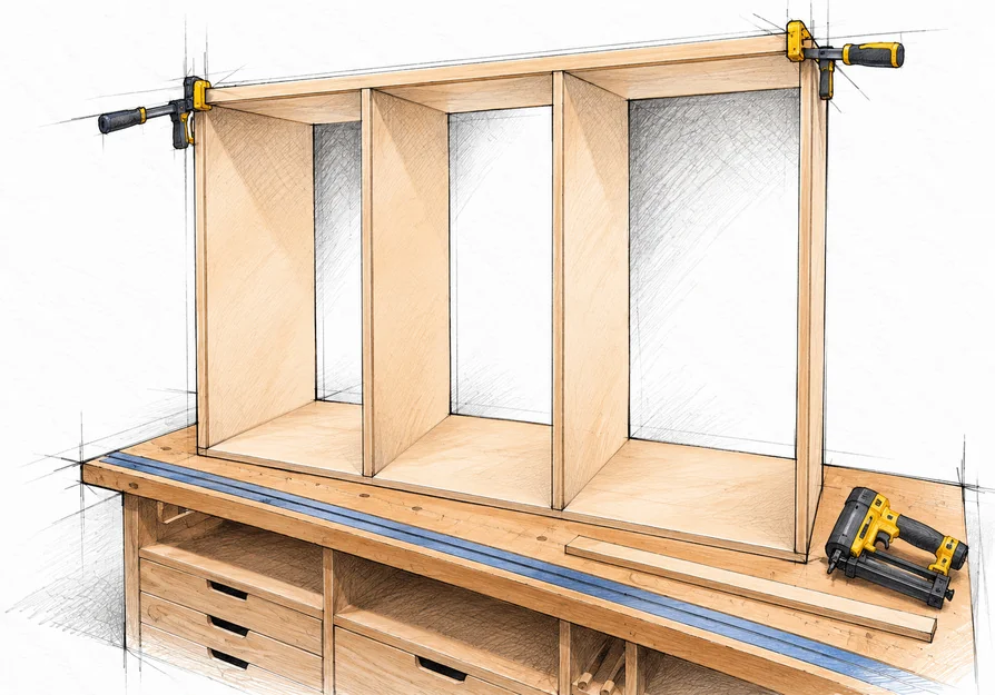
Clamp the dividers flush · Storage Unit with Beveled Edge
Close the glue joint
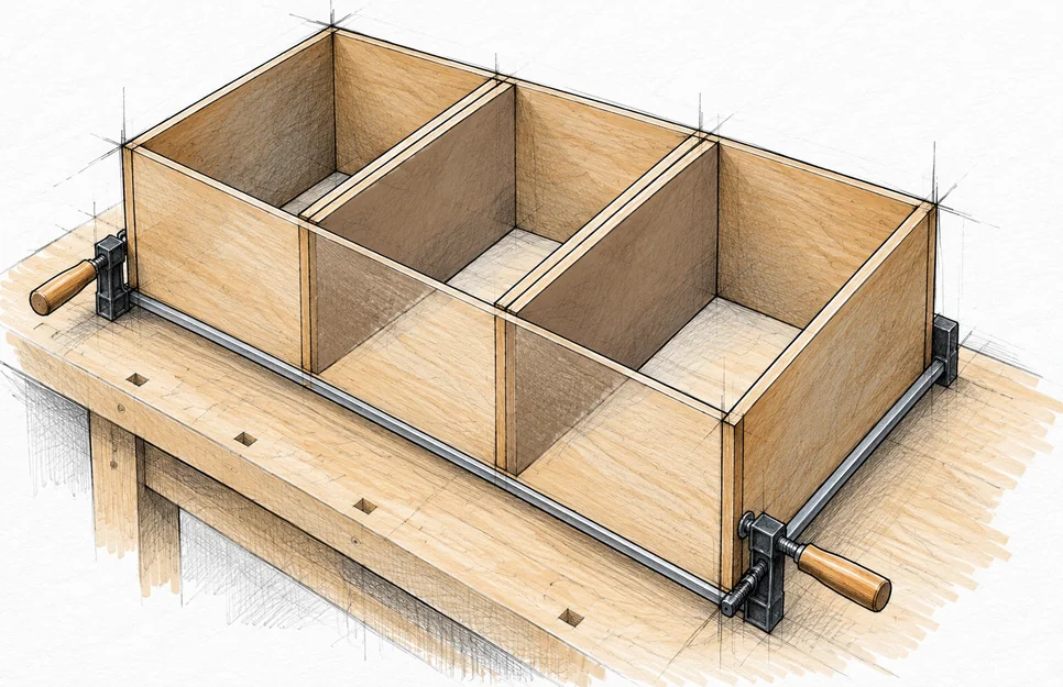
Use padded clamps to hold the layers together without bowing them. Confirm the front edges remain flush along the full height. Remove squeezed-out glue before it hardens.
Allow the glue to cure
Follow the glue maker’s clamp and cure times. Clamps hold the joint while it cures; do not treat a few small nails as a substitute for a sound bonded surface.
Install the three shelves · Storage Unit with Beveled Edge
Mark equal openings
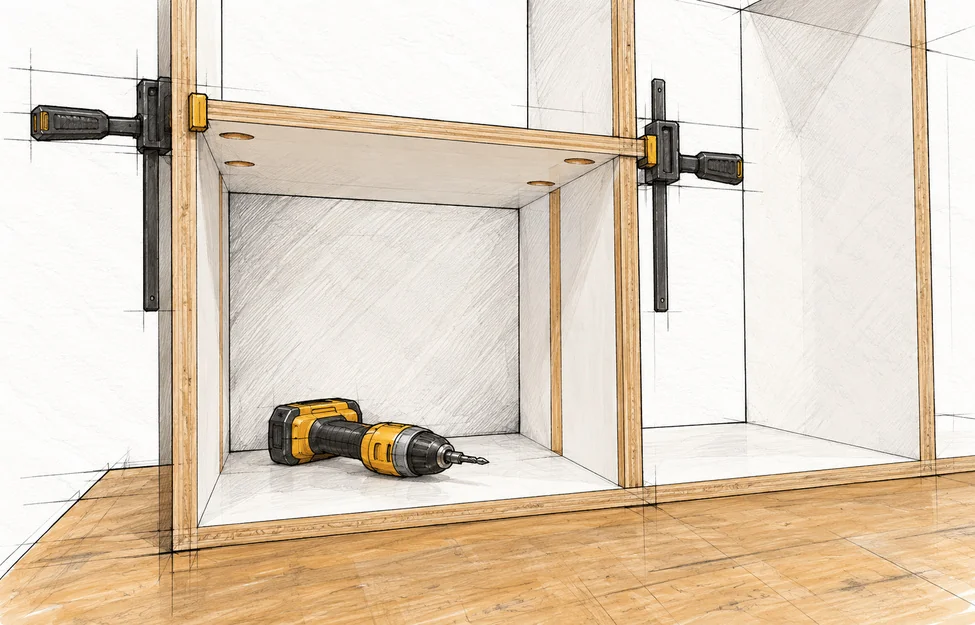
Measure 17⅛ in (435.0 mm) up from the inside bottom of each bay to the underside of its shelf. With a ¾ in shelf, the upper clear opening is also 17⅛ in.
Fasten from below
Drill pocket holes on each shelf’s underside at both ends, following the jig instructions. Clamp the shelf level and flush at the front, then install 1¼ in (31.8 mm) pocket screws.
Check the shelf alignment · Storage Unit with Beveled Edge
Dry-fit before fastening
A shelf should enter without forcing the dividers apart. If actual plywood thickness changes the opening, fit the shelf to that measured space. Keep the intended equal bay layout.
Use a straightedge
Check all three front shelf edges together. Their top surfaces must align and the shelf ends must be fully seated. Repair a stripped joint before adding trim or the back.
Prepare the bevel strips · Storage Unit with Beveled Edge
Test the profile
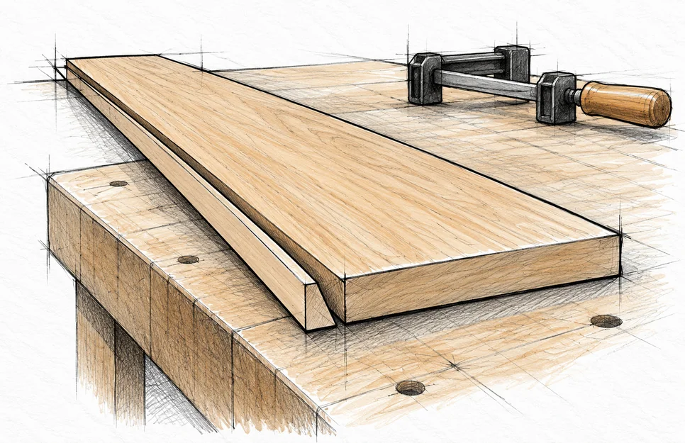
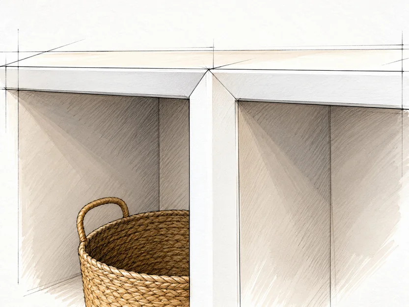
Set up a 30° bevel rip in scrap first. The trim covers a ¾ in (19.1 mm) panel edge; verify the profile against the real plywood before cutting the long blanks.
Plan all six rips
Account for blade kerfs and safe remaining stock width. Keep grain along each strip. Exact finished trim lengths and nail spacing are not specified. Leave the strips long, then measure and miter-fit them to the assembled edges.
Rip the trim safely · Storage Unit with Beveled Edge
Prepare the machine
The illustration is a static setup, not an operating guide. Follow the saw manual for bevel cuts, guarding and the riving knife. Use a suitable narrow-rip jig or push blocks and stable infeed and outfeed support.
Stop before a risky cut
Keep hands away from the blade path. Never make the last strip from stock too narrow to control safely. Have a competent operator make these cuts if the setup is unfamiliar.
Fit the beveled trim · Storage Unit with Beveled Edge
Fit one edge at a time
Measure the actual front edges, cut the required miters and dry-fit the trim. Match the bevel direction at every corner and divider. Do not force an open miter closed with nails.
Attach without shifting
Apply glue, hold the strip flush and attach with 1¼ in (31.8 mm) 18 ga brads or 23 ga pins. Check nail direction in scrap; avoid driving through an exposed face.
Keep the corners crisp · Storage Unit with Beveled Edge
Inspect the dry fit
Look along the front for a consistent bevel, tight joints and no raised edge. Support the thin strips when cutting. Make small fitting adjustments instead of filling a badly mismatched joint.
Prefinish option
This view shows trim fitted before the shelves. That sequence can improve access for painting. Keep the same three-shelf layout and fit the shelves after the separate parts have dried.
Fit the plywood back · Storage Unit with Beveled Edge
Square the case first
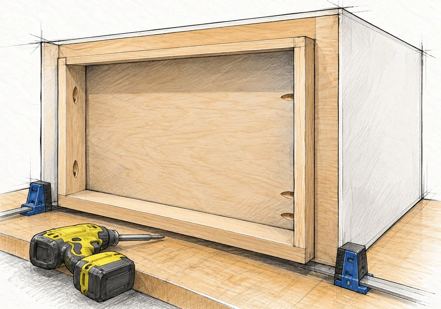
Place the back on the rear of the case and compare the case diagonals. Adjust until square, then center the 59½ × 36¼ in (1511.3 × 920.8 mm) panel so its edges remain supported.
Mark the supports
Transfer the centerlines of the perimeter, doubled dividers and shelves onto the back. These lines locate solid support for the brads. Do not guess where the hidden plywood edges lie.
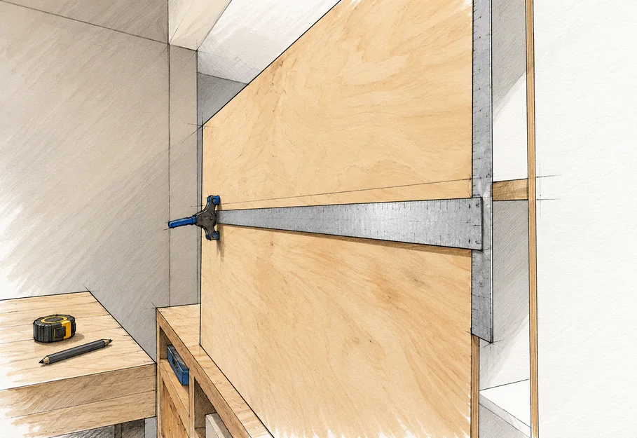
Mark the fastening lines · Storage Unit with Beveled Edge
Transfer the actual positions
Measure the installed shelf and divider positions, not just the nominal plan. Use a straightedge to mark light lines on the back over the center of each supporting edge.
Confirm edge support
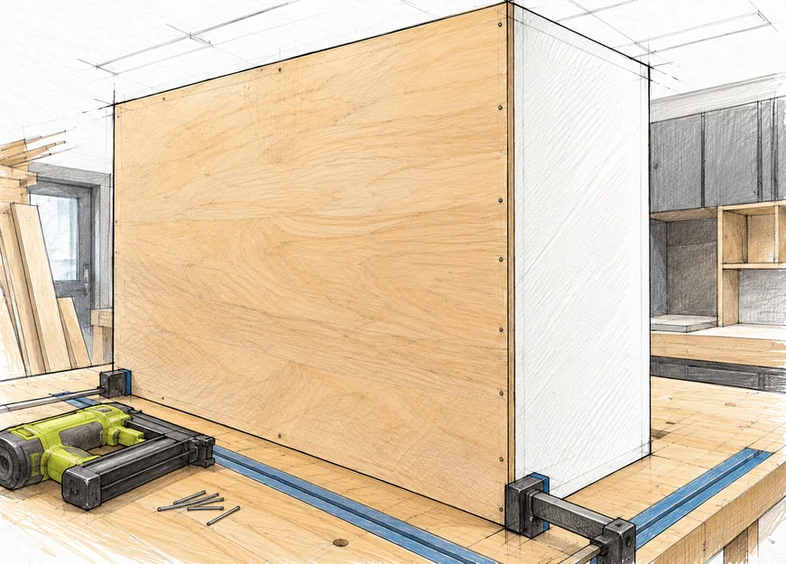
The back must overlap the perimeter everywhere. Recheck that the case is square before fastening. Keep pencil marks light enough to remove or cover during finishing.
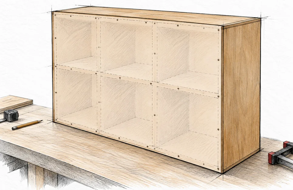
Secure the back panel · Storage Unit with Beveled Edge
Fasten into the case
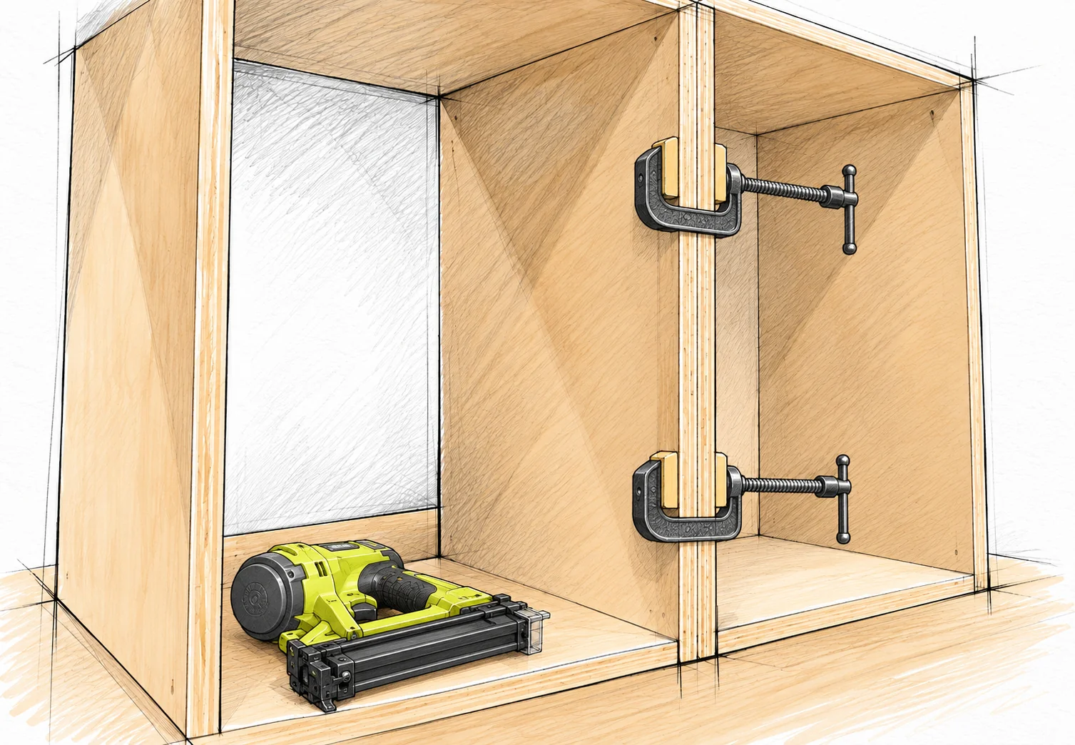
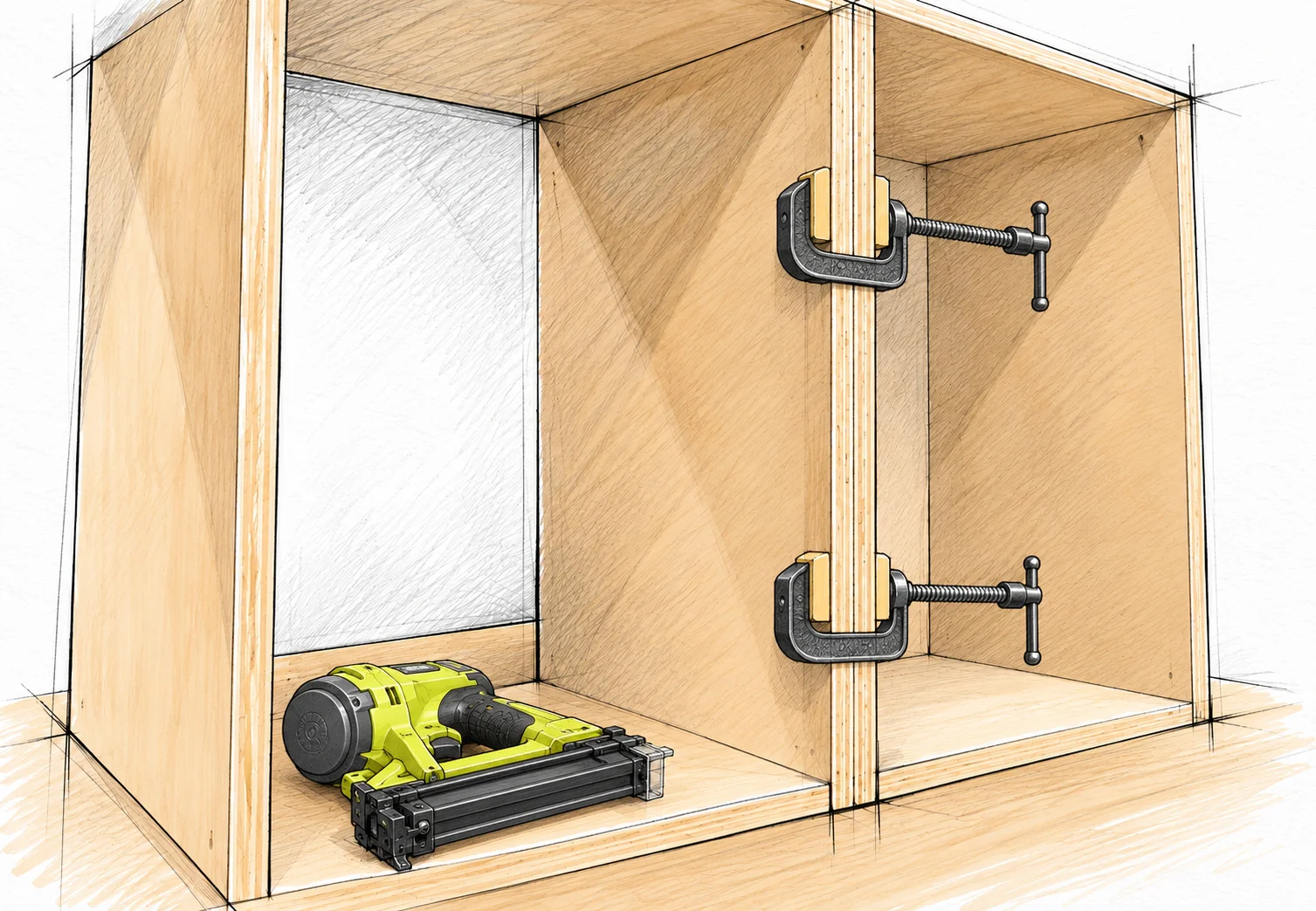
Attach the back with 1¼ in (31.8 mm) 18 ga brads along the perimeter and the marked divider and shelf supports. Use the nailer maker’s settings and a scrap test to avoid overdriving.
Inspect both faces
Keep hands clear of the exit path. Check inside every cubby for a missed edge or protruding nail; correct defects before painting. The thin back alone is not an anti-tip attachment point.
Fill and sand the surface · Storage Unit with Beveled Edge
Fill small defects
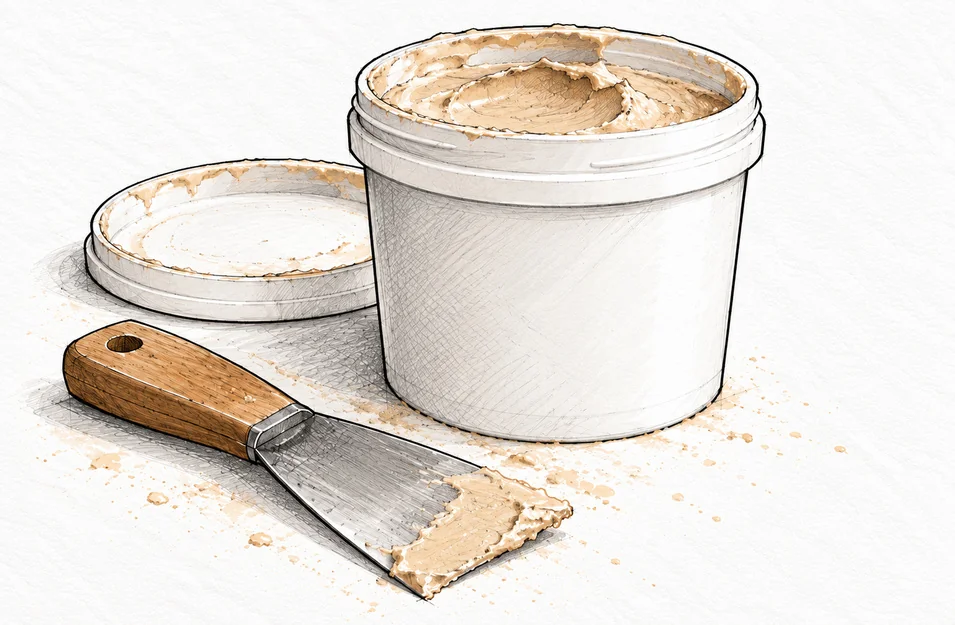
Fill nail holes and small surface joints beside the trim with paint-compatible wood filler. Let it dry as directed, then sand the filler flush without rounding the bevels or cutting through plywood veneer.
Prepare for primer
Remove dust thoroughly. Structural gaps need a sound joint repair, not a thick layer of filler. Test primer and paint on scrap to confirm adhesion and the desired finish.
Prime and paint the parts · Storage Unit with Beveled Edge
Use the open access
If prefinishing, coat the case, shelves and back separately while the openings are easy to reach. Keep future glue surfaces bare. Protect the bevel edges and let the finish dry before assembly.
Follow the finish system
Use a compatible primer and paint. Brush, roller or sprayer setup, ventilation and protective equipment must match the products. Observe their recoat and cure times. Drying depends on the coating and workshop conditions.
Caulk the interior joints · Storage Unit with Beveled Edge
Seal cosmetic seams
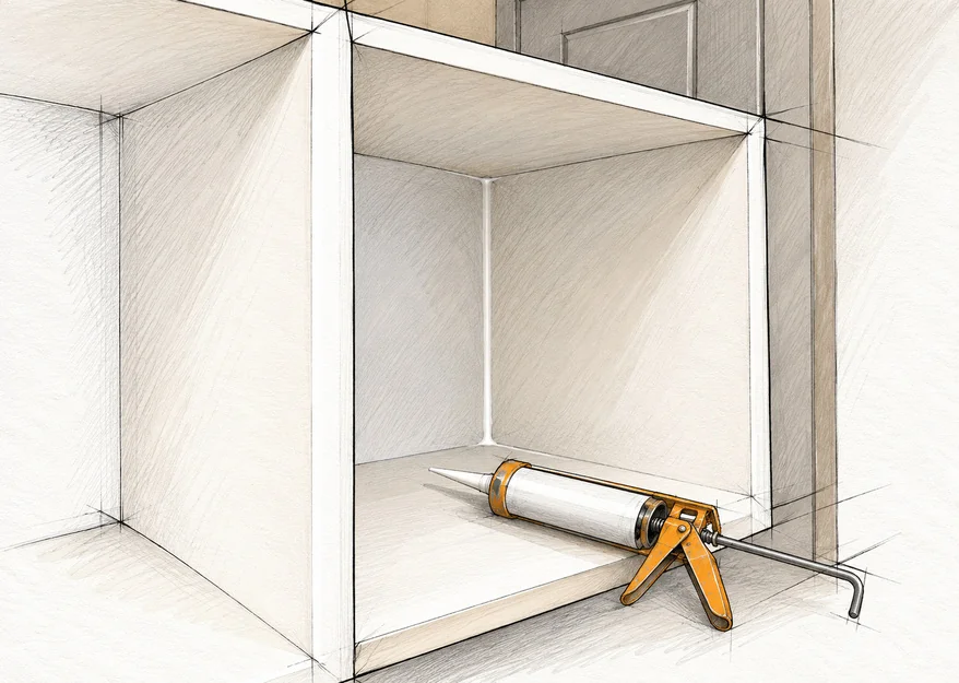
After the back and shelves are installed, apply a small neat bead of paintable caulk to compatible interior joints. Smooth and clean it as the product directs. Caulk is not a structural adhesive.
Complete the topcoats
For colored finishes, caulk before the final paint coats. With white finishes, confirm any visible caulk matches or paint over it. Allow all coatings and caulk to cure before loading the cubbies.
STEP 07 / RECESSED SUPPORT
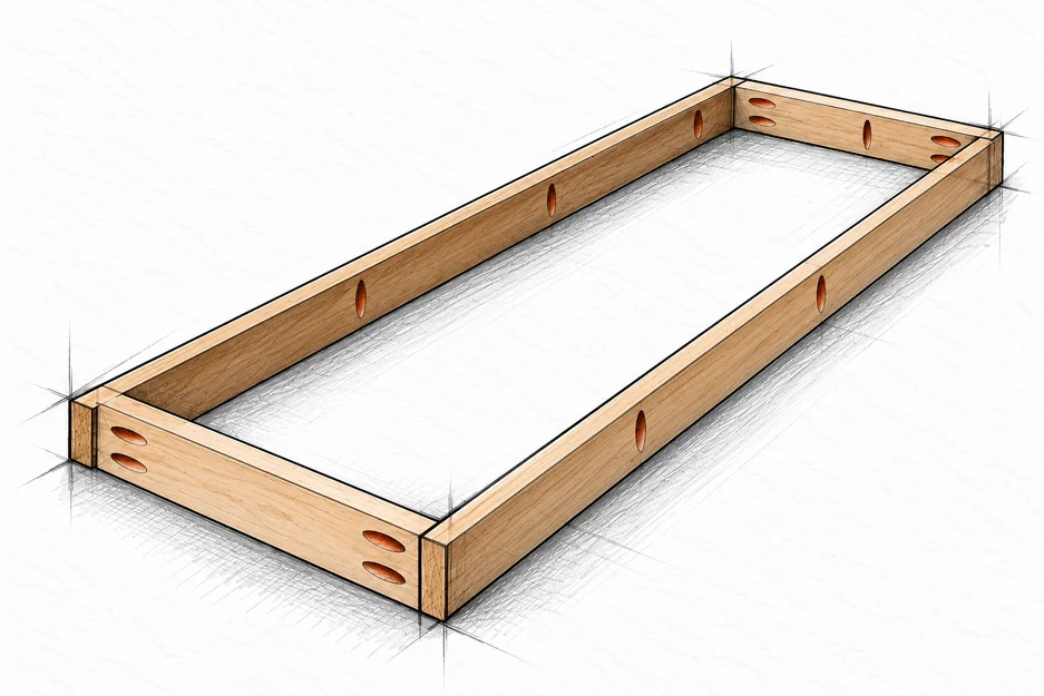
Assemble the base frame
E × 2 at 56 in / F × 2 at 13 in / Glue / Pocket screws
Assemble the base frame · Storage Unit with Beveled Edge
Keep the short rails between
Orient the 1 × 2 rails so the frame is 1½ in (38.1 mm) high. Fit the two 13 in (330.2 mm) F rails between the 56 in (1422.4 mm) E rails. The outside frame is 56 × 14½ in (1422.4 × 368.3 mm).
Prepare both kinds of holes
Drill corner-assembly pocket holes and upward-directed holes for later attachment to the case. Keep the attachment holes facing the same side. Glue, clamp square and join with 1¼ in pocket screws.
Check the four rail frame · Storage Unit with Beveled Edge
Check the rectangle
Compare the base diagonals and check it sits flat without twisting. Both short rails must be between the long rails, not across their ends. Keep the outside size consistent at both ends.
Leave access for attachment
Verify that the upward pocket holes remain reachable with the driver. Let the glue cure as directed before handling the base or turning the cabinet onto it.
Center the base underneath · Storage Unit with Beveled Edge
Support and mark
With help, lay the empty case on a padded, stable surface to expose its bottom. Center the base: 2 in (50.8 mm) from each end and 1¾ in (44.5 mm) from the front and rear of the 18 in carcass depth.
Attach the frame
Clamp without damaging the finish. Drive 1¼ in (31.8 mm) pocket screws through the prepared upward holes into the bottom panel. Check the actual screw path and depth in scrap before fastening.
Secure the base to the case · Storage Unit with Beveled Edge
Check before each screw
Keep the frame tight to the underside while driving. Do not allow a screw to collide with another fastener or break through the cubby floor. Stop and correct any stripped or misdirected screw.
Set the unit upright
Lift with help rather than dragging the base across the floor. Check for rocking on the intended surface and correct the support before anchoring. Do not load the unit yet.
Check the overall fit · Storage Unit with Beveled Edge
Inspect the structure
Check all joints, shelf attachments, trim, back and base. Remove sharp edges, proud fasteners and splinters. The case should be square and stable, with no rocking or visible joint movement.
Leave room for safe storage
Choose baskets to the actual finished openings and leave clearance for easy removal. Keep heavier contents in the lower cubbies. Do not overload or climb on the unit.
Inspect the bevel junctions · Storage Unit with Beveled Edge
Look and feel along the edges
Check that miter joints meet neatly and no trim corner stands proud. Touch up filled holes and finish defects with compatible products. Avoid sanding away the crisp bevel profile.
Wait for full cure
Let repairs and coatings reach the manufacturer’s stated cure before inserting baskets. A surface that feels dry may still be too soft for regular use.
INSTALLATION REFERENCE
Anchor before use
Wall-specific anti-tip system / Structural attachment
Anchor before use · Storage Unit with Beveled Edge
Secure the furniture
Install a suitable anti-tip system to appropriate structure in the case and wall, following its manufacturer’s instructions. Do not attach only to the ¼ in back. Get qualified help if wall type or fixing strength is uncertain.
Keep the unit safe
Keep the top free of tempting climb-to items, especially around children. This is not seating or a ladder. Recheck anchors and joints after moving the unit and during regular use.
FINISH AND INSPECT
Complete the safety check
Final structural check
Confirm every shelf is secured, the back is fully supported, and the base is tight and square. Check inside all six cubbies for projecting nails or screws. Repair any looseness before the unit is put into use.
Confirm the wall attachment
The anti-tip device must connect sound furniture structure to suitable wall structure with the correct fixings. Check for concealed services before drilling. The sketched installation views do not replace the anchor manufacturer’s instructions.
Use and care
Wait for the finish to cure fully. Load gradually, keep heavy items low and stop use if the shelves deflect or any joint moves. No verified weight capacity is provided. Clean with products compatible with the finish and keep the unit dry indoors.
After a move
Empty the cubbies, disconnect the anchor only when the unit is supported, and lift with help. Re-level, inspect and reconnect the anti-tip system at the new location before reloading.
 Read the build steps